Saturday, 26 October 2013

Commodore 64 DRAM Repair

This is an old post, preserved for reference.
The products and services mentioned within are no longer available.

I have a Commodore 64 in for repair at the moment that is showing some intermittent memory faults. For once, it doesn't seem to be the PLA. The same fault has been seen with a working PLA and the PLA from this unit working fine in a test C64 board.
There is evidence of a historic memory repair. Some time in the past it looks like 4 of the DRAM chips were replaced.
In the process, a couple of tracks must have been lifted as there were a few wire mods on the back of the board.
Looking at the replacement chips, all four of them are different makes and part numbers, and are different again from the four remaining original chips! The data code of the original chips and the rest of the board is 1983, the new ones look to be around 1986. I don't know if they were done one at a time, or if the repairer couldn't find two the same.
The way these are used is that each of the eight 4164 chips is 64K by 1 bit, which together make the 64K by 8 bits required. The originals were NEC D4616C-2, and the replacements were a KM4164A-15, a TMS4164-15NL, a Hitachi HM4864P-2, and an OKI M3764-20RS. All 5 parts are compatible with the standard 4164 part, but their timings are different. I always try to match the part number, manufacturer and if possible the date code, so that they perform the same so there are no timing glitches caused if one chip is marginal faster or slower than another.
In order to test this further, I removed all the chips and replaced them with sockets, repairing the previously damaged tracks.
I then installed a matched set of working 4164 chips (TMS4164-15NJ) and away we go, the Commodore 64 is working again. 38911 bytes free as their should be.
The chips I removed have all separately tested as working, I think it was just a slight difference in timing or a bad connection on one of the repaired tracks. The assortment of chips will be useful to keep though, to add to my collection of assorted DRAM chips used to find matching replacement chips for future repairs.

Saturday, 12 October 2013

Z80 CP/M Single Board Computer

This is an old post, preserved for reference.
The products and services mentioned within are no longer available.

Following on from the Z80 Single Board Computer I previously built, I've now turned this into a computer which can run CP/M. This was a popular alternative (and predecessor) to DOS in the early 1980's. It ran on most Z80 or 8080 based computers, many of the multiple board S100 backplane type systems from the late 1970's / early 1980's, such as the Altair 8080 and the RML 380Z. Some home computers of the day had add ons which allowed them to run CP/M, such as the Torch BBC Z80 second processor.
Later ones could run it natively (the Commodore 128, the Amstrad CPC 6128). Much software was written for CP/M, but it lost in the end probably due to the graphics capabilities and standardisation of the IBM PC. Display support in CP/M was a bit patchy as it seems every machine had a different display with different capabilities, so there were often multiple variants of the software for different feature sets. They also had various disk formats and so again, multiple versions may be required. DOS had clearly defined MDA and CGA displays, and disk formats (see here for everything you ever wanted to know about disk drives - but were afraid to ask), so was easier to support.
Huge thanks here to Grant Searle, for his CP/M on breadboard page, upon which this is based. He has put a lot of work into that and provided clear instructions and all software required to get up and running.
The starting point was the original Z80 SBC I built previous. The top half of the breaboard remains basically the same with ROM, RAM and CPU. The EPROM is different, with Grant's CP/M BIOS and ROM BASIC. The ROM is larger (16K as opposed to the 8K on the plain BASIC SBC), so has an additional address line - which I had forgotten and it took me quite a while to realise that. Beneath, the 6850 UART is removed, to be replaced by a Z80 SIO. However, the new SBC also has disk storage in the form of a compact flash card, and the advice is keep the cables short, so that has been placed there, close to the Z80 CPU.
The clock remains (although using different gates) and there is fuller address decoding with a 74138 giving 8 I/O blocks. The serial IO is provided by a Z80 SIO/0 chip, giving two serial ports. One is used to connect to the PC via an FTDI serial cable, the other is connected to the TV and keyboard interface as before.
When initially fired up, the flash card is blank, so ROM BASIC is available, and it runs as the previous Z80 SBC. When connected up to a PC serial terminal, you can setup the CP/M system on the CF card, and then transfer software over. Grant has provided quite a neat mechanism for doing this, with a PC application which generates a text file with the software converted into hex codes, and software which sites on the CP/M side which reassembles the hex into applications, ready to run. One of the first things I tried was Richard Russel's BBC BASIC for CP/M.
The next step is to build this up onto a board, just waiting for a few parts.

Monday, 7 October 2013

Keyboard Error, Press F1 - IBM 5160 Part 3

This is an old post, preserved for reference.
The products and services mentioned within are no longer available.

When I last wrote about the IBM5160 I was in the process of stripping down and rebuilding, it turned into a brief history of disk drives, mainly because I didn't have an XT compatible keyboard. The system was sitting there showing keyboard error (301) and requesting F1 be pressed to continue.
Although it had the same 5 pin DIN connector, the XT had a different keyboard protocol to the AT standard, which is still in use today, only the connector has changed from the 5 pin din on the AT to the 6 pin mini din connector on the PS/2.
Both protocols (the nice, elegant XT one and the later overcomplicated AT one) required only two pins, a clock and a data pin. I had started to design a simple converter using an 8 pin AT Tiny microcontroller. When looking for further information on the protocols, I came across this thread on the Vintage Computer Forum. It appears I'm not the only one in this predicament, and someone had already designed such a device, using an 8 pin PIC. Rather than reinvent this particular wheel, I programmed the firmware supplied by Chuck(G) in this post into a PIC12F629 and built the circuit on breadboard. It worked first time. Further information and schematics here.
I had removed all the drives and most of the cards and had only just started putting bits back together, so with no boot device available, the 5160 loads Microsoft BASIC from ROM.
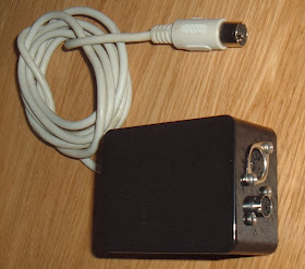
A quick bit of testing and the keyboard is working fine, so I built it up into a little box.
A 5 pin cable plugs into the XT, and there are two options for a keyboard to plug in.
Either an older AT style keyboard.
Or a recent PS/2 keyboard.
Adding the drives back and trying a DOS disk, booted up into DOS and away it goes.
I also had a try with the hard drives. Initially they were reporting problems, but I found an old copy of Norton Disk Doctor and set it going.
It didn't seem to like the CGA card, so I tried another and got the same result. Must not be compatible, so I dug out an 8 bit compatible VGA card and tried again.
That sorted out the problems and started booted into DOS 6.22. However, it then started some type of 'Power Menu' which wouldn't do anything without a password. I tried the usual candidates, but didn't manage to guess it. Easy enough to bypass though. I need to copy off things like software for the 'AST MegaPlus II' card, and then go for a clean install of DOS and all my usual software. Drives of that vintage are rather noisy and delicate, so I'll will probably mothball these as they are and look at using something like a compact flash card.
The power supply is likewise rather noisy, I've started stripping that down, with a plan to potentially replace the fan with a quieter one. I've noticed a couple of X type mains filter capacitors which have a habit of exploding, BBC model B's suffer from that a lot. I'll replace those, give it a good clean and check out the rest of the capacitors before putting it back together.
There is also a bit of a bodge where one of the disk drive power cables has been cut and and extra power cabled spliced in and the joints wrapped in cloth tape. I'll probably try to undo that mod and return it to its former condition.
Read more in the next article....

2022 Update: The next article will arrive at some point. I really must get around to getting all the 5160 bits out of storage and build up a working machine.

Friday, 4 October 2013

VIC20 Repair Revisited

This is an old post, preserved for reference.
The products and services mentioned within are no longer available.

A while ago I wrote an article about how, in the dim and distant past before I had a decent EPROM programmer, I had repaired a problem with a faulty VIC20. As well as a few corroded chips and bad connections, the Kernal ROM had failed. This was a 24 pin 8K mask ROM, and at the time, the only solution I had was to use a 27C64, a 28 pin 8K EPROM in a socket adapter. The result, although successful, was less than elegant.
Since then, I've managed to get hold of some MCM68766C25 EPROMs, which are pin compatible with the original mask ROM, and a far more elegant solution. The only problem is, since they are rather old and obscure EPROMs, none of the programmers I have support them. So, it's time for another adapter, but this time, one that only needs to be used on the programmer. Rather than make yet another variation of 24-28, 28-24, etc., I decided to make a 'universal' one. Most of the left hand, and half of the right hand pins are consistent across nearly all the devices, so I created an adapter with sockets to allow all the other pins to be wired with jumpers.
This is only going to be used for reading and writing on the programmer, so I added a ZIF socket to the top. It can then be wired appropriately for the task in hand, sit in the programmer, and have the necessary chips inserted in the top.
This turned out to be useful when I was checking through a load of potentially suspicious ROMs from a couple of 8032-SK's which were non-functional. Out of the 12, 2 were dead and 2 were slightly wrong (but slightly wrong in an identical way, I need to investigate that further). It also allowed me to program some 2532 EPROMs (which are pin compatible with the Pet 4K mask ROMs) as temporary replacements
Anyway, back to the VIC20. The standard 8K EPROM, the 27C64, has 3 enable lines and a separate VPP pin, but the 68766 has a single pin for enable and VPP. One solution would be to build a simple transistor circuit to use the enable pin to switch VPP to the G/VPP pin on the 68766. However, I went for the easier way of setting the programmer to 27C512 mode. That standard chip also has a single G/VPP pin, so it just needs to be set to only program the first 8K. Mine has the option to skip 0xFF bytes, so can actually work over the full range. The spec of the chips says 25V in 2mS pulses. The closest I could get was 21V in 1mS pulses, it took a couple of goes, but it worked in the end.
Once programmed, the chip is then a direct replacement for the original mask ROM, so can be used without an adapter. It's not the most elegant way of programming it, but seems to be the cleanest end solution.
The VIC20 is then up and running again.