Saturday 27 June 2015

Commodore 8032 Mainboard Repair

This is an old post, preserved for reference.
The products and services mentioned within are no longer available.

Another 8032 board in for repair. I seem to be doing quite a few of those at the moment. They never fail to disappoint in the range of weird ailments. It's the traditional black screen, no beep, a generally dead computer. The owner has previously attempted to get this running, replacing four of the ROMs with 2532 EPROMs, and replacing the four 2114 video RAM chips.
There were a few suspicious looking solder joints, but these boards can be difficult to work on, so that is understandable. Usual first tests, power, reset, clock all came out OK, although the reset pulse was a bit slow, three or four seconds, it's normally a second or so. So time for the ROM/RAM replacement board.
With the ROM/RAM board in place and set to replace the onboard ROM and RAM the system booted. Checking individually, there was a fault in the RAM, and with the RAM replaced, the onboard ROM would beep, but not show anything on the screen. This usually means the kernal is getting somewhere, but not far enough along to start BASIC. The other issue was the screen.
Quite a nice pattern, but that's not much use. Looking closer, it appeared the text was being displayed, but the right hand half of each character was a solid block. You can just make out the 31743 bytes free and ready prompts.
The 80 column video circuit on the Pet is quite complex, and there is a lot of odd / even split, and it uses pairs of 2114 SRAM which are 4 bits wide each to give the 8 bit character. It's very tempting to start looking at all the odd and even bytes parts, and the buffers that only affect half of the byte. The section outlined in red is the video circuitry, and most parts of it operate on only odd or only even, or on half bytes.
But you have to stop and think about the Pet. It has no pixel graphics capability. All of the above things are working at the character level, so when they go wrong, you don't get half a 'b' in 'bytes', you get half of the bits that make up the character code for 'b' (0x42), so it won't be a 'b' at all, but 0xF2 or 0x4F if the bits are stuck on, 0x02 and 0x40 if they are off. That isn't what is happening, it's actually in the pixel that make up the 'b', and that narrows it down to only two candidates, the two chips on the left of that red box, the character ROM and the 74166 shift register.
Testing that was easy. I removed the character ROM, and I still saw half blocks on the screen, so the culprit was the shift register. This takes a line of the bitmap of the character from the character ROM and sends it out to the screen a pixel at a time. Replacing that and the display was restored.
Well, I say restored, there were a few random characters, usually @ symbols on the screen. This seemed to get worse when the screen was scrolled. This is a simple test program that is meant to alternate \ and / characters to make up a random maze, but the more it scrolls, the more @ symbols appear.
I went to a simpler test program:
10 PRINT ".";
20 GOTO 10
This produced a screen half full of dots as expected by also a random collection of letter n's.
Here '.' is 0x2E in PETSCII and n is 0x4E, and on the boot screen, @ is 0x00  and it should be space (0x20). It looked like one particular bit was wrong in the value being fed to the character ROM, so it could have been the input buffers or output latches or the 138 that does the timing not pulsing the write for long enough. But, it did look like it was the video RAM. It could have just been one bad bit on one RAM chip, but there were some n's that were on the alternate characters (i.e. .n.n.n.n would mean just the odd or the even, ..nn.. would mean both). I replaced all the video SRAM with good chips, and it was fine. The 2114 that had been replaced passed memory tests, but I think were just a bit slow to cope with rapid screen fills. With the video RAM replaced, and the screen was back to how it should be.
Now I could get on with the rest of the testing. Memory tests showed one faulty 4116, so I replaced that with a similar spare. This time I soldered it in place, as these MOSTEK ones all seem to have short legs and it didn't sit well in a socket. You'd hardly know it was there.
The ROMs were still not able to boot. I tried a full set of known working 2532 EPROMs, and got the same result, so I tested for continuity and found a few bad connections. I decided the best approach was to removed and replace all the ROM sockets.
The tracks underneath were in good condition, and all continuity tests passed with no sockets, so I installed a new set of sockets and tested with a set of known working ROMs. That worked, so I want back to the set of 2532's that came with the board, and they all worked as well. With those labelled up, it was back in business, running on it's own ROM and RAM.
Further testing showed no response from the IEEE-488 port with one of my pet microSD disk drives plugged in, and no response from either tape. Oh, and it is still slow to reset. Tape 1 came back after cleaning the connector, I've found the best way with those is to re-tin them with fresh solder, and then wick most of it back off with solder braid.
I cleaned all of the connectors and but still no tape 2 or IEEE-488. The IEEE-488 connector is gold plated, so I didn't want to tin that, I checked for continuity, and all the connections were going through.
I used the debug output from the pet microSD to check what was coming through, and it was getting a request, but the handshaking wasn't working. I could see the name of the file I had tried to load, so the data lines looked OK. That rules out one 6520 and two of the MC3446's. The one chip that does handshaking and tape 2 is the 6522. I removed and socked that and installed a new 6522 and that brought back the IEEE-488 port and tape two.
So that's it pretty much sorted, other than the slow reset. I had noticed some of the capacitors were in a poor state, including the one on the 555 that generates the reset signal. I don't normally replace the capacitors on Pet boards unless they appear damaged, or are not preforming properly. In this case it was both, the covering was shrunk and split on several of them, that usually means they have got rather hot at some point. I went though and replaced all the electrolytics, bar the large one, as that seemed OK and is difficult to get one with the right lead spacing.
Testing the caps, some were still OK, but several were out of tolerance and had quite a high ESR.
With those replaced, the reset was back to how it should be, and all was working. Well.
A long soak test and lots of testing and it's ready to go back.
The final list of faults was as follows:
  • RAM - 1x4116 DRAM replaced
  • ROM - all ROM sockets replaced, all ROM and EPROMs tested OK
  • Video half character blocks - 74LS166 replaced
  • Video random characters - 4x2114 and sockets replaced, 
  • Tape - edge connectors cleaned
  • IEEE-488 - 6522 socketed and replaced
  • Slow boot - recapped

Wednesday 10 June 2015

PET microSD 8032-SK internal fitting guide

This is an old post, preserved for reference.
The products and services mentioned within are no longer available.

This post has been left for historic information. The PET microSD is no longer in production. The replacement SD2PET is available now, more information on the pre-order page.

Here is a bit more information on installing one of my new PET microSD Commodore PET disk drive replacements inside a Commodore 8032-SK or 8096-SK.
The normal PET miroSD has an edge connector soldered to the board, and plugs into the rear of a 4032 or an 8032 or similar.
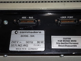
The 8032-SK doesn't have edge connectors on the rear, it has IEEE-488 connectors.
Inside, it is actually the same board as the normal 8032, but it is rotated 90 degrees, and had cables connecting the user and IEEE-488 ports to the rear panel.
The 8032-SK version of the PET microSD does not have the edge connector soldered on
The kit includes the board, a power cable and a riser.
Temporarily remove the rear panel cable and the riser board can be installed where it used to connect.
There is then a special slot on the riser into which the pet microSD connects. The connections on this socket have been reversed for this purpose.
The pet microSD rests above the board, supported in the socket. Make sure it is not making contact with anything below, there should be a clear gap.
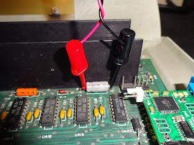
Power is taken from capacitor C11, the grey one in the photo above. The polarity is marked on the board and the capacitor. The black 0V rail should be clipped onto the lead near the edge of the board, and the red 5V lead to the other end, marked + on the board. If it doubt, check with a voltmeter.
The other end of the power cable connects to the pet microSD, again with black to the edge of the board, and red marked +. Here it a closer view, with a piece of white paper behind for clarity.
The original rear panel cable can then be reattached to allow other IEEE-488 devices to be attached to the pet as normal.
The edge connector on the top of the riser board is the now the same as the original edge connector, so connect the cable in the same orientation.
From the side, you should be able to see how all this fits together.
If you would like to order an 8032-SK kit or indeed a normal pet microSD kit, contact me.

2022 Update: I have since designed a much nicer SD drive for a PET. The SD2PET is available from  The Future Was 8 bit Note there is not a version which will fit the 8032-SK.

Monday 8 June 2015

pet microSD - Commodore Pet SD card disk drive

This is an old post, preserved for reference.
The products and services mentioned within are no longer available.

This post has been left for historic information. The PET microSD is no longer in production. The replacement SD2PET is available now, more information on the pre-order page.

Update: The PET microSD is now available to buy, there are also some new versions for different models of PET.
This is a disk drive replacement for Commodore Pet range of computers, the 2001, 3000, 4000 and 8000 series.
Plug it into the IEEE-488 port of one of these machines and it will work as a standard Commodore disk drive, so all the standard BASIC commands such as LOAD "$",8 and SAVE "FILENAME",8 etc. will work. As will the BASIC 4.0 extensions such as DIRECTORY and DLOAD "MYFILE".
Unlike the petdisk clones I built previously, these boards are based on PetSD by Nils Eilers. This is a much better design that uses proper IEEE-488 bus drivers to connect to the PET, so should co-exist happily with real Commodore disk drives.
The original PetSD was based on SD2IEC, a very popular disk drive replacement for the Commodore 64 and other computers with the 6 pin din IEC connector. This has a very stable code base, with good support for file and access types, and D64 disk images etc. Nils has forked the SD2IEC code to produce NODISKEMU, and that is the firmware that is running on the PET microSD. It is compatible with the original petSD firmware as well, but the new code is recommended. This firmware is still under development, and can be updated as new versions are released by placing the update files on a microSD card - no programmers are required. There are various new products soon to be available in the world of pet disk drives. Dave Stevenson has a useful comparison matrix.
There are various connection options. The standard version will plug into the back of a 2001 / 3000 / 4000 / 8000 series pet using the IEEE-4888 edge connector. Power is supplied from the datasette drive connector.
Alternatively, power can be supplied by clipping into a reservoir capacitor inside the pet, with the cable fed out next to the connector.
This gives a slightly neater appearance, and frees up the rear datasette port.
The standard edge connector version with either power connector is £50.
The 8032-SK and 8096-SK do not have the edge connector at the rear, so there is a version for them which fits internally. Inside, it's the same board as the 8032, but the edge connector is not externally accessible, it has extension cables connecting the edge connectors to GPIB IEEE-488 connectors on the rear.
The pet microSD can be installed via a riser board which has an edge connector at the top to allow the original rear panel cable to plug in.
The 8032-SK internal mount version is £60.
For those with multiple Pets, there is a version that can be used for either 8032-SK internal mounting, or with a different riser card, on the standard pet edge connector.
The multi connector kit is £70, and comes with both risers and both types of power connector.
Finally, the 8296, 8296D and some early 8032's have a 24 pin header connector on the board. Pet microSD can be supplied with a similar header to allow internal mounting in one of those machines, although this is currently untested.
The jumper on the side can be removed to make the SD card read only. The 6 pin header on the side allows connection of an FTDI or similar serial cable. Currently this is used for debug, but there are some interesting future plans for that.
Please contact me if you would like to order one of these.

Update:
I've now written a pet microSD user guide.

Update 2:
The new batch of pet microSD boards, in blue, also include a datasette power connector with passthrough.

Update 3 :

There are now some new versions for different models of PET, including internal mount. That link has buy it now buttons.

2022 Update: I have since designed a much nicer SD drive for a PET. The SD2PET is available from  The Future Was 8 bit