Friday, 30 September 2016

Commodore PET ROM RAM boards

This is a new version of my 6502 ROM RAM boards, this one specifically for upgrading or replacing ROM and/or RAM inside a Commodore PET.
To use, remove the 6502 CPU from it's socket and plug in the PET ROM RAM board. The original CPU then plugs into the socket on the PET ROM RAM BOARD. It can now replace all the system memory (32K) and ROMs.
I have been making various versions of this for a while now, this new PET ROM RAM is a smaller version of the 6502 ROM/RAM boards. It allows you to replace the ROM and RAM in a Commodore PET to either bypass faulty parts, or upgrade an existing system. So if you have a PET with faulty RAM you can use this to replace that. You can also use it to upgrade any PET from a 2001 with 8K and BASIC 1 onwards to the full 32K RAM and BASIC 4. (BASIC 2 or 4 is required to use an IEEE-488 disk drive, such as the PET microSD).
Although this is smaller than the full size board, it has all the same chips, the RAM chips is now hidden under the ROM.  It does have fewer DIP switches, so cannot be used to select individual ROMs or banks of RAM to replace, but for most users, it will only be used to enable all the upgrades and run at full capacity. The original versions are still available if you do need to diagnose faults.
The DIP switch options on this board are as follows:

  1. RAM enable, switch on to bypass the original RAM and use the full new 32K RAM
  2. ROM enable, switch on to bypass the original ROM and use one of the new ROM sets
  3. ROM select
  4. ROM select
  5. ROM select
These are supplied with ROMs for both the original range of Commodore PET machines without a CRTC chip (6545), starting with the original 2001, and the 2001N range, 30xx, and the 9" 40xx machines, includes the PET tester ROM, BASIC v1, BASIC v2 and the final BASIC v4.0. The other 4 ROM selections are for later CRTC based PETs, the 12" 4032 and 8032 machines. This includes 40 and 80 column ROM sets for Business and Normal keyboards (note you need 40 column hardware to use 40 column ROM sets and 80 column hardware needs 80 column ROMs).
The board is supplied with a double sided pin header socket which plugs into the bottom of the board and fits into the original CPU socket. The pins are thin like IC legs, so shouldn't cause any damage to the sockets, they are not the big square pins used for jumpers etc.

These boards are available to buy from my Tindie Store.

2022 Update: The PET ROM/RAM boards are still available from my SellMyRetro store

2024 Update: PET ROM/RAM Boards are back at my Tindie store
You can order one of these boards below, select the appropriate options and within the UK or international postage.


Price including postage:

Sunday, 11 September 2016

Nintendo SNES Mini power supply repair and upgrade

This is an old post, preserved for reference.
The products and services mentioned within are no longer available.

Bit of a change, here we have a Nintendo SNES Mini. Marked SNN-CPU-01, it is an imported NTSC version, and has had some power supply problems. I am told it came with a 'US' power supply, and the owner had cut the cable off a that and attached it to a 'UK' power supply.
When used like this, it blew the fuse, inside there should be a white ceramic 1.5A fuse, but that has gone leaving just one end cap in place.
On investigation, it seems for 'US' supply, read 'DC', and for the 'UK' replacement read 'AC'. The case is marked (slightly confusingly) AC Adapter DC 10V. This is however a DC input.
The adapter that had been modified is Nintendo, and says it is for use with a (super) NES control deck, but is 9V AC.
It looks like these is space on the board for some additional components to support AC input. A large capacitor footprint and a single diode, both to the left of the regulator. There is also space on the other side for an RF modulator which isn't fitted on this version.
First step is to replace the fuse. Rather than a ceramic one shot fuse as originally fitted, I have used a polyfuse which will reset after the fault condition has cleared. This one is a 1210 style case and fitted in the original footprint. I've gone for the same 1.5A rating as the original, and a 16V voltage limit.
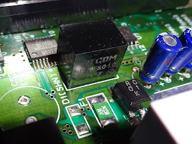
The large heatsink has been removed to give clearer access. Attached to it was a standard 7805 regulator. Given that probably took the brunt of the reverse currents that blew the fuse, that should be replaced. Again I've gone for a modern replacement. This is a RECOM R-78E5.0-1.0, which is a drop in replacement for a 7805.
These are switch mode regulators, which means they are a lot more efficient than the original linear 7805 and no longer require the heatsink. It also just about halves the current consumption of the unit (260mA with the 7805, 160mA with the 78E5.0).
Initial testing just showed a black screen, so I did worry that something might have been fried. Then I remembered it was Nintendo. I cleaned the contacts on the cartridge and socket and tried again and then it started up without a problem
I didn't have a replacement DC power supply with the appropriate connector, so I went for the same cut and rejoin approach. I was going to fit a line socket, but I thought that could lead to future problems if the supplies were separated and the wrong one plugged in.
I used one of TheFutureWas8Bit's ZX Spectrum power supplies, as these are 9V, 1.5A which is more than enough for this unit. The original was nominally 10V DC, but that would have been unregulated and that sort of supply can vary from 8V to 12V depending on load. 9V regulated is a good option as it would give sufficient overhead for a linear 7805, and is within the 7-28V input range of the new regulator.
It is also marked with the centre negative polarity used by the Spectrum, which matches the way the original connector is wired. I've added a label to the case so there is no confusion in future.