Sunday 26 May 2019

Epson Equity LT Laptop - Part 1

This is an old post, preserved for reference.
The products and services mentioned within are no longer available.

25 years ago, I started University, hard to believe I know, given I have such a grasp of modern technology. I had an Amiga 500 that had served me well throughout my A Levels, but my parents had decided it should be passed on to my younger sister (who promptly sold it to one of her friends - I was very upset and don't think I have fully recovered). The University had lots of computers, so I was planning to use those, but I did end up with a laptop. Sort of.
This isn't it, but it was a similar model, an Epson Equity LT. It had belonged to one of my dad's friends, and the screen had been damaged. He asked me to have a look, and I got him a few quotes from PC repair places to get a new screen. I think they were sufficiently expensive that he bought a new one instead, so I was left with the laptop, minus a working screen.
Handily, the screen detached, so I was able to remove the useless broken screen section. I was a poor student (boo hoo, but I am still accepting donations), so couldn't afford to get the replacement screen. There was a connector for an external monitor, 9 pin so monochrome or CGA, but I didn't have one of those either.
It also had a serial port, and what I did have was an old BBC Micro and a black and white TV (see above, poor student, 1994 etc.). So I remember I hooked it up with a DOS boot disk set to redirect the console to the serial port, and a terminal program on the BBC. I'm going to have a go at recreating that. Bit first, I need to have a look at this laptop. I have had an ebay saved search running for ages, and it finally turned up one of these, although this is a different model, it is the posher version.
The one I had was an NEC V30 8086 clone with 640K RAM and two 720K floppy drives, one on each side. This one is the same except that it has only one floppy and a 20MB hard drive instead, but it's not in the best of condition.
It does however power up, count up all 640K of RAM, but then flags up an error that the time and date is not set. This is a late 80s machine. It will have a battery inside. Oh dear. Better have a look at that.
It doesn't like 2019, so I set the date to 1989 and it seems to have DOS 3.3 installed, along with Lotus 123 and a word processor called Galaxy.
The hard drive is ridiculously loud, I guess I'm so used to fanless SSD systems these days. Right, time to get inside and see if we can find that battery.
OK, there's a lot going on there. The main battery pack looks like 8 C cells, 9.6V at 2000mAh, I'll look at replacing that with new NiCad cells at a later date.
I've spotted the CMOS battery, but it's going to need a few bits removing to get to it. That board is the hard drive controller. I was hoping it might be an 8 bit IDE drive, but it doesn't look like it. The expansion slot is propriety, so I'm not going to be able to easily fit an XT-IDE type board, so there goes my chance of replacing it was a compact flash card.
The drive I think is a JVC unit, 20mb, 26 pin connection. New one on me. (more info on the JVC JD-3824LOYO drive in this blog post: https://knm.org.uk/blog/2017/04/the-jvc-26-pin-hard-disk-interface-part-1/
Ah, there's the battery. I'm pleased to say it hasn't leaked, that can be such a problem on machines of this era. This one is a 3.6V lithium cell in AA form with leads soldered to tabs.
That measures 0.0V on the meter, so we can assume it is well and truly dead. I fashioned a replacement from a new AA 3.6V cell in a battery holder. That will save me soldering new leads on in 20 years when it next gets replaced.
The holder is screwed in place using the screw which used to hold the P clip on the old cell.
Whilst I'm inside, here's the heart of the beast, a 5 year old CPU design at the time, still going strong.
Some DRAM chips providing the 640K RAM, and two 8K EPROMs with the BIOS.
Putting that back together, everything is still working, and it should now be able to remember the date and time. Wow, that hard drive is screachingly loud.
So, what's next. Well, after waiting ages to find one of these, another has come along, this time the dual floppy (i.e. quiet) version. That looks in better condition, but is listed as not working. I'm sure there's a plan forming here. I also need to sort out a BBC Micro with a terminal ROM and I think I have the original serial cable I used somewhere in one of the many collections of "things which might come in handy one day".

Sunday 12 May 2019

Picicle Build - Handheld RetroPie Console

This is an old post, preserved for reference.
The products and services mentioned within are no longer available.

This is the Picicle, a kit I saw on Tindie, and thought it would be interesting to build.
Looks very nice when completed, but needs a little assembly first.
The kit unpacks into a PCB, several bags of surface mount parts, the case in the form of four cut sheets of perspex and one sheet of button shapes.
What is no included is a Raspberry Pi Zero W (because you still don't seem to be able to buy more than one at a time), a battery (because postage is tricky) and a microSD card.
Assembly of the PCB was a little tricky due to lots of small surface mount parts, 0603 resistors and caps, and ICs in SOT-23  and SOIC 8 packages.
I think I did well not to lose any of them, although one resistor did go flying and took a while to locate. In the end, I found it because it was 0603. Most of the other parts I have dropped were 1206, so the smaller part stood out.
The LCD is attached with a flat flex, soldered direct to the board as a connector would take up too much space.
Also on the front in a single speaker for the audio (most of the circuitry along the bottom is an audio amplifier circuit).
The Pi mounts on the back, not a technique I've seen before, there are surface pads for the 40 pin connector on the Pi, and you just flood solder through the holes so it flows the pad beneath and makes a connection with no height lost for a header connector.
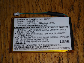
The battery was tricky to find, the build instructions show a 405060 cell (4mm high, 50x60mm), 1800mAh LiPo. I couldn't find one like that, but I did find a 1250mAh 503759 (5mm high, 37x59mm), that was sold as a replacement battery for a GPS. That will do for the moment, I might upgrade if I can find something larger but still no more than 5mm thick.
Always a little scary when you have to cut the battery wires and solder to the board. These LiPo cells don't like their output to be shorted (although this cell does have the protection PCB on the end). The chips on the left hand side of the board form a battery charger circuit, powered from a mini USB socket below. The red and green LEDs on the front indicate charging status. The blue LED is an under-voltage warning.
The buttons were pushed out of a single piece or perspex, and the edges filed down.
Next step was getting the case together. The instructions talk about using UV glue to attach the top two laters together, and setting under a UV lamp. I haven't heard of UV glue before, so I cheated and used a couple of pieces of double sided tape instead.
The whole thing is held together with five screws from the back.
These are M3, and the they pass through two of the holes on the Pi, which are M2.5, so they need to be drilled out to 3mm.
With that, time to try it out. All looking good, the speaker is working, and the display has been correctly initialised (it is driven via SPI, rather than the usual HDMI output). The instructions link to an SD card image which is preconfigured for the audio, video and control settings, just add games.
This is where I hit a bit of a problem. I couldn't get it to connect to any WiFi networks, not even open ones. Not sure what I was doing wrong? I ended up copying the ROMs directly onto the microSD card and away we go.
I wasn't sure how well the display would respond, being an SPI interface, but it's fine even on a fairly fast game like Sonic.
That all works very nicely, quite a neat little console. I'll need to sort out some suitable ROMs and try see what it is like playing for a while, and what sort of battery life it gives.
All in all, a very nicely designed kit, the soldering skills required mean this is not suited to the absolute beginner, but it's good afternoon project with a neat little handheld console to play with once you're finished. Only suggestions would be gluing with parts of the case in advance, as UV glue is not something everyone has. Also, a schematic would be nice.

The kit is available from the sellers Tindie store - https://www.tindie.com/products/Picicle/picicle-kit/ 

Update:

Following further testing, it's all working nicely. Battery life seems to be around 5 hours on the 1250mAh LiPo cell I fitted.
When the battery is running low, the blue LED comes on (driven by a MAX809T, which is actually a reset chip, but is quite effective here as it's output goes low when the voltage falls below a threshold, which is just what you need for a low battery indicator).
When charging, the red LED comes on.
Charging from a USB 2.0 port took about 2.5 hours, after which the green LED lights.
It's important to use the mini USB jack on the bottom side for charging, and not the micro USB ports on the Pi. These are connected to the cell, so would feed that with too high a voltage. LiPo cells don't like that and tend to get a bit upset about it and swell to twice their size and catch fire.
To be sure that doesn't happen, I have blocked off those ports with a suitably sized piece of PCB material that is clamped in place when the case is screwed together.
2022 Update: Looks like this kit has now been discontinued.

Monday 6 May 2019

Update rollup

This is an old post, preserved for reference.
The products and services mentioned within are no longer available.

There have been quite a few updates to existing products recently, so I thought I'd do an update rollup. In true Microsoft style, please don't turn off your computer, this may take a while

Minstrel V2.7

I am now shipping V2.7 Minsterl ZX80 clone boards. Changes since V2.6 include the removal of the 24/28 pin ROM selection option - I don't think anyone was using it, so I remove it to save having to fit the three wire links, and to avoid confusion (several people had forgotten to fit the links).
I've changed the NTSC jumper from a 2 pin into PAL/NTSC 3 pin jumper. The PAL position doesn't do anything, but it stops you having a loose jumper if you aren't using NTSC mode.
I have also added a position to add the optional resistor that reduced the video signal level for some TVs that are a bit picky.
You can fit the resistor on the back, or on the front, but it's not marked on the front, so it's not obviously missing if you don't fit it - most TVs don't need it.

IEEE-488 Diagnostics

The board has been updated to include test points for meter / scope / logic analysers. The white bordered pins are ground. The rest are the 16 signal lines.

Dual USB joystick - internal version

I have added the internal mount version of the dual 9 way D USB joystick adapters. This uses two flying leads with sockets on to suit cases with 9 way D cutouts at various spacings - even different sides of the case.

Userport save / power monitor / SD2IEC power / etc.

The Future Was 8 Bit Userport saver has been expanded to have all sorts of other superpowers. 
Now includes:
  • extending the userport to save wear from frequent use
  • a pin header for user port expansion
  • a reset button
  • a voltmeter monitoring the 5V rail
  • a method of powering an SD2IEC without typing up the datasette port
https://www.thefuturewas8bit.com/shop/commodore/userport-saver-sd2iec-power.html

Clear C64 cases

Also just about visible above is the new clear versions of the C64 cartridge case.
These look rather nice, don't they.
https://www.thefuturewas8bit.com/shop/commodore/c64romcart.html


SD2PET

That's about it for updates.
I'm still working hard on the SD2PET.
Here are a few more photos of the SD2PET Future, currently in testing.
https://www.thefuturewas8bit.com/shop/commodore/sd2pet-future.html