Sunday 28 April 2019

Acorn Electron Repair - Part 2 Keyboard

This is an old post, preserved for reference.
The products and services mentioned within are no longer available.

This is the second part of the Acorn Electron repair. Last time I got the main board working after it arrived in this state. Looking at this photo, you can see the colour difference between the two halves. I would guess that someone had two Electrons, one with a broken keyboard, and one with a faulty main board, and guess which two halves I have here?
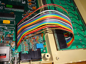
Now it is time to look at the keyboard. The Electron has a very nice keyboard, a metal frame with individual keyswitches soldered onto a single sided PCB. This is connected to the mainboard via a 22 way ribbon.
This is quite unusual, I don't recall seeing this type of cable anywhere else. You can see quite well here how it is constructed as due to the damage, it has started to delaminate.
There are two layers of clear plastic sandwiching some bare copper strips, crimped at each end.
Here the connector is cracked, but just about holding together. In order to test it, I've put sellotape on both sides to try to hold it together.
The back of the PCB has some foam tape to protect the ribbon from the pins on the back of the PCB. With that removed, you can see the where the cable is connected, the fourteen diodes and four resistors. I check continuity through the cable, and most pins were connecting, but there seemed to be the possibility of a couple of shorts where the copper ribbons were close.
I decided to test it with one of my USB keyboard controllers as I know that it is protected against shorts on the pins. On the Electron, fourteen of the pins are connected directly to the address lines, so any shorts could damage the board. (there are diodes to protect the address lines from shorting in operation, but they are on the keyboard PCB, so any shorts in the cable could cause problems).
The keyboard appears to work, but not all the keys, it's a bit intermittent, and there is a danger of shorts, so I think I'll go for replacing the cable. I'm not aware of a supplier of this sort of cable, so I am going for a more easily available alternative.
First off, I removed the cable, and soldered in a pin header to the keyboard. Space is a little tight, so I went for a straight header soldered in at an angle.
The connector on the Electron end is also a pin header, with the same standard 0.1" spacing.
To connect those, I've used Harwin M20 (also called Dupont and various other things) crimps and headers. I didn't have a 22 way, so I used a 20 way and a 2 way.
I tested this again on the USB keyboard controller, and all but a few keys were working.
The ones that were not responding are usually just dirty contacts in the switches. Unless there's a pattern, like a whole row or whole column, in which case check the connections. You can also test this by shorting the two pads for a switch on the back if the PCB, which will effectively press that key.
Where a particular key doesn't work, most of the time they just need to be pressed a few times to brighten up the contacts. If that doesn't help, pull off the key caps with a key puller and give it a quick squirt with contact cleaner. Put the keycap back and press it a few times and they usually come back.
The keys were all now working with the USB keyboard controller, so back to the Electron. That is a straight connection to the main board, but it's fairly tight in there.
In order to make it a bit easier, I've split the ribbon cable into individual wires, so they all lie flat to the side and the case closes fine.
With all that back together and a bit of a cleanup it's working nicely.
The obligatory 10 PRINT program gives the expected results.
Time for a bit of testing.

2022 Update: Did you spot the prototype SD2Elk in one of the photos? I don't think anyone did at the time. The idea was basically add a userport to the Electron and use a BBC Userport SD solution. The worked with a few tweaks to the code, but so much software wouldn't work as it was all originally tape based and didn't work when the disk interface used extra RAM and moved page up. I was looking at various solution to that, but finally ditched the project when I saw that someone else had released something along similar lines. I was unsurprised to see a review from Chinnyvision which basically concluded that none of the games he wanted to play worked for exactly the reasons given above.

Tuesday 23 April 2019

Acorn Electron Repair - Part 1 Main Board

This is an old post, preserved for reference.
The products and services mentioned within are no longer available.

Lesson one in how to pack a computer: supermarket bags for life do not make a good packaging material.
Lesson two: try to remember to plug in the connectors and fit at least some of the screws.
It looks like the keyboard ribbon has been damaged, but let's leave that for the moment.
At first glance, the rest of the machine looks fine, issue two Acorn Electron with almost everything soldered directly to the board
One thing that wasn't soldered to the board, but should have been, was the RF modulator. It is looking a bit dodgy, wobbling around loose. Looking on the back of the board, you can just make out the cracked dry joints where it used to be soldered in.
What I hadn't noticed at first is the power cable has actually broken off as well. I would guess that as the modulator got looser, the owner would have wiggled around the TV lead in order to get a picture. That's never a good idea as it usually gets worse, and I think it this case has lead that wire fraying and finally breaking off.
The wire at the top is the composite video input, just a wire passing through a plastic grommet. The other wire is some kind of pass through capacitor, built into the case, so I didn't think I would be able to reattach it. Since I had a selection of spare UM1233 RF modulators removed after composite mods, so I fitted one of those.
In order to test the board, I borrowed a keyboard from another Electron and switched it on. A quick check around power, clock and reset were all behaving as normal, but it wasn't booting up, just showing some random(ish) characters in 32 character repeated pattern.
Before I go further, I should explain that it's important to have a keyboard plugged in as the Electron will not boot without one. The only other machine I can think that has the same issue is it's big brother, the BBC micro. They keyboard circuitry is very different, but neither OS will not progress beyond a blank screen with no keyboard present. (OK, some will boot, but many won't, the pins are left floating, so it depends on variations in the particular silicon in the ULA)
If you are used to working on Commodore or Sinclair machines, you wouldn't bother with the keyboard until you get to the stage where you have a READY or a K promt on the screen, but it's easy to then forget (or to not be aware) that Acorns won't. There is a brief mention of this in the service manual, but that should probably be a in bold at the top of each page.
The Electron keyboard is a 4x14 matrix, the 14 columns generated by the address lines A0-A13, and the 4 rows being read by the ULA. On the keyboard, there are pullup resistors on those input lines, and without those being present, the boot routine stalls.
In the past, I made a little dongle that plugged into the keyboard connector with those four resistors present (and a power LED for good measure). I couldn't find that, no idea where it is now, probably still plugged into an Electron board somewhere, so I made a new one.
I put this together on a spare bit of pad board, and as well as the four 15K pullup resistors, I added a green power LED and reset switch. As a bit of an afterthought, I added the red LED as the caps lock LED, and the right hand switch which presses shift+caps lock (which can be done with a single switch since they are on the same column wire). The idea being if the OS is running, it will toggle the LED, even if the screen display isn't working for whatever reason.
This plugs into the left hand side of the connector, and picks up pins 1 through 9 which has all the signal required. I tried it on a known working board, and it successfully does the job of replacing the keyboard and letting it boot.
As expected though, it doesn't help the faulty board in question, but it makes it easier to work on without having to keep plugging in a keyboard to test. The caps lock LED stays on and there is no response to shift + caps lock.
The random pattern on the screen is a bit unusual, Electron faults are usually black screen, or sometimes white screen, and those are usually caused by the ULA. This combines most of the IO, video generation and RAM management in the Electron.
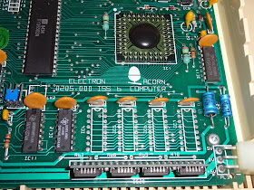
 Under the metal cover is a ceramic chip.
You can quite often revive an electron by just cleaning the contacts and reseating the ULA.
They changed the socket type on these issue 4 boards, the chip is the same 12C021M as used on the earlier issue 2 boards, and they also suffer from the same issues.
By the time of the final(?) board revision, issue 6, they had changed to so soldered in blob chip, so that should be more reliable.
The RAM on this issue 6 board also used an alternative SIP module, with the same 4164 chips on.
4164? but there are only four of them? Well, that's one of the cost reductions in the Electron that was maybe a step too far. The 4164 is 64K by 1 bit. The Electron has four of those, and the ULA preforms two read/write cycles for each bit to get 32K by 8 bits, so memory access is half the speed it could be.
And the RAM is where I am currently looking for the problem with the faulty issue 4 board (remember that?). Probing around, the address lines on the chips were all wiggling around nicely, and the data pins (pins 2 and 14 on each chip) looked fine on three of the chips, but one wasn't moving at all.
That looked a likely suspect, so I replaced IC5 with a good working 4164 and tried it again.
Now that the board is working, it is going to be worth repairing the keyboard. Had it been a faulty ULA, I already have several boards that are fine other than a bad ULA, so would have just filed it along with those.
This has already gone on too long, so tune in for part 2 where I repair the keyboard.

Sunday 14 April 2019

ZX81 with early ULA

This is an old post, preserved for reference.
The products and services mentioned within are no longer available.

Slightly unusual blog post today. Here's a broken computer I'm not going to fix.
It's a ZX81 in not too bad condition, but with one of those aftermarket keyboards on. These give it a sort of ZX Spectrum 48K style feel.
It would originally have been stuck on, but the adhesive has dried up over time and it fell off easily.
The rubber keys press down on the original ZX81 membrane, so underneath is a standard ZX81.
This one is not working, so time to venture inside.
For once, the keyboard membrane tails don't look too bad.
This is an issue 1 ZX81 board, but quite an early one. The giveaway is the ULA.
This is one of the early ones with only a date code, no other labelling. So we know this one was produced sometime shortly after the 11th week in 1981.
Most of the issue 1 ZX81 boards after this had Ferranti labelled ULAs, 2C184E versions, and most of the chips were socketed.
Back to the earlier board, and the ROM is also soldered in, and I think is also an earlier buggy version.
The Z80 is an original Zilog part, dated even earlier, 30th week 1980.
The RAM is difficult to read, a Mostek MK4118 8038 date code?
It is at rather a jaunty angle. All the bits must have fallen down to one side.
The 5V is there, and there is a clock and the Z80 is doing stuff, but the screen is white. Testing with an external RAM pack makes no difference, so it's probably not the internal RAM, or at least not only the internal RAM.
It's looking like the ULA is faulty, and it's not socketed and soldered in. I've got (many) other ZX81s, so I don't need this one to work. It would be a shame to remove the ULA and replace it, or even to straighten up or replace the RAM, as that would make it just the same as any other issue 1 ZX81, so in this case, I think I'm going to leave it alone.