This is an old post, preserved for reference.
The products and services mentioned within are no longer available.
This one is a little different, in that it does not have a modulator inside a metal can like most other 2600 boards.
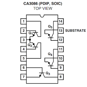
There is one IC in the modulator section, uA3086PC, which I initially thought would be an RF modulator chip, but when I looked around, it turned out to be a transistor array.
So basically five transistors in an IC package, two of which are matched and arranged with a common emitter to form a long tail pair. Looking at the schematic of the 2600 Junior, these are drawn as discrete transistors inside a box.
There is a lot going on there, so here is a simplified version, which can be applied to most the 2600 systems I have seen. (the exception being the four switch 2600s where they tried to cut costs by removing the 4050 buffers, the picture quality suffered and they were back in the 2600 Jr). Various parts have been omitted for clarity, mainly pullup resistors.
Here you can see the TIA chip has three luminance outputs, a composite sync output, a colour burst and finally an audio output. The luminance and sync outputs are buffered via 4050 gates before being merged with the colour burst signal. An audio subcarrier oscillator is applied to the audio signal from the TIA and is also merged at this point to give composite video and audio which is then modulated by the RF oscillator to generate the UHF TV signal. (OK, that's very generalised, but you get the basic principle).
In order to get clean composite video and separate audio, these elements need to be separated, which can be done without cutting any tracks, just by removing a couple of components. There is normally an 18K resistor connecting the decoupled audio signal from the audio subcarrier oscillator, so removing that detaches the audio signal. It is best to pick this up after the decoupling capacitor to protect the TIA. The modulated audio is usually connected to the composite video signal via a 1K8 resistor, so removing that again separates the two. The final task is to disable the two oscillators to save power and reduce noise. Usually accomplished by removing the transistors and power feed.
On the actual schematic, you can see the parts highlighted to be removed. R48 disconnects the audio. Removing Q4 will stop the audio subcarrier oscillator. I would normally also remove the variable inductor that powers the oscillator (which is normally the tall red coil), but in this case L8 is in a metal can which would be a little more effort to remove, so I have gone for the two polystyrene 820pF capacitors (C53,C54) instead. Removing the transistor array chip is one way to disable the RF oscillator, but it is easier to remove a few passive components instead. Removing the transistor next to the IC (Q3) disconnects power from the rest of the transistors, so that should stop it oscillating, and R17 and C33 disconnect that from the signals.
The following parts were removed: Q3, Q4, R17, R48, R56, C33, C53, C54.
For a neat modification, I am using the Future Was 8 bit Deluxe Composite Video mod kit (currently on offer at £10).
The board mounts at the back where the RF output jack used to sit. Raised up on a couple of foam pads.
The four wires are connected to composite video (yellow), audio (white), power (red) and ground (black). There are usually several suitable points to connect each one to. I normally choose the closest or neatest to wire.
Power can be tapped from a via above the removed C33 which carries a clean 5V supply, and ground and composite video can be tapped from the pads of C33. The audio is tapped from the top of R48.
As ever with these things, keep the wires short. We supply the kits with a good length of cable to allow installation is as many devices as possible, but generally, the wires should be cut short, and kept out of the way of any of the digital ICs.
Another example is this 4 switch 2600, the board is positioned with nice short cables, and so that the supplied AV lead can run out the case through the same hole the original RF lead did. See my previous post on Atari 2600 Composite Video Mods for more examples, including the metal can modulator version of the 2600 Junior.
This 2600 is all done and ready to go back into it's case.


