
I have a new kit listed on my Tindie store. PET Composite Video Out.

This replaces the previous version (left) which was only available pre-assembled.

With the new version, I wanted to simplify things a little. The old one had various jumper blocks to provide buffered or buffered and inverted versions of all the signals, to both the video output and a second output for a monitor. I don't think anyone ever used any of those.

It also had the "seemed like a good idea at the time" pre-made links on the jumper blocks, so it would work as is, or you could cut the track and fit the jumpers. When I used that on the jumpers on the Minstrel, lots of people skipped over that in the instructions, fitted the jumpers over the pre-made links, then wondered by the jumpers didn't work.
The new version bypasses all of that and contains only the bits that you need.

It is available in kit form if you want to built it yourself.

Its quite a simple through hole kit, so you should be OK if you know which end of the soldering iron to hold and have made sure you throw all of your lead-free solder in the bin before you start.
Or you can still order it assembled if you prefer.

It plugs into the monitor connector of a PET 2001 or 2001N.

Anything with the 9" monitor should work, 2001/2001N/3008/3016/3032/4016/4032.

It is not suitable for 40xx or 80xx PET/CBM models with 12" monitors and 6545/6845 CRTC chips. Those generate different frequencies and have different polarity signals. And no, it will not work with a SuperPET (since someone always asks with everything I do - maybe if someone could send me a SuperPET I could make things for it?)
These earlier PETs all used something very similar to NTSC (yes, even in the UK and other PAL territories).
16.625ms frames, give a 60.150Hz frame rate, close enough.

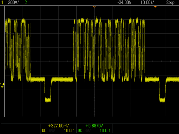
The vertical sync shown on the bottom trace, is the correct polarity, active low, and around the right pulse duration. That's a good start.

The video at the top is active low, so needs to be inverted so that the white pixels are high.
The horizontal sync in the middle is the wrong polarity, active high. This is easy enough to fix, but where things get tricky is the pulse starts too early, is way too long, and ends well into the visible video data.
Because of the timing of this horizontal sync pulse, the previous version had the video shifted slightly to the right on the screen. This was usually not a problem, and could usually be adjusted by the horizontal position control of your monitor if it bothered you.

It is only noticeable on my monitor if I turn the brightness right up on a screen full of text (which you can easily generate if you run the board without a CPU).

I have built various versions of PET Video Out over the years.

Most of which have been based on a vintage circuit from Commodore PET Users Club of England – Newsletter issues 1 and 2, page 9.

Note the version you normally see of this has this capacitor marked as 2200mf, this is incorrect, and should be 2200pf, or 2.2nf as we would normally write these days. I have corrected the version above.
That was my starting point, with only a minor change of adding the 100Ω resistor to drop the output level slightly.

To get around the issue with the horizontal sync pulse, an RC circuit (R1/C4) is used to generate a short pulse at the start of the PET's hsync pulse.
The bottom trace shows the rising edge at the start of the PET's horizontal sync pulse.
The middle trace shows the output of the RC circuit.
The top trace shows the horizontal sync pulse that is generated for the time the middle pulse is over the logic threshold. It this case, around 3µs.

This is then combined with the vertical sync by a NOR gate to generate an active low composite sync. This shows the start / end of the frame with the vertical sync pulse.

The capacitor / diode arrangement (C5/D1) turns this composite sync into negative pulses on the output. That is combined with the inverted video signal to give a composite video signal. It fits reasonably well to the expected -0.3V sync and +0.7V white level.

This new horizontal sync pulse is still too early, so it causes the video to be offset to the right slightly.
To fix that, I need to generate an initial delay pulse and use that to trigger the actual HSync pulse.
I wondered if I could do that without adding too many parts, but I only have a spare NOR gate?
I have used the spare NOR gate and a new RC circuit to create a the middle pulse in this capture, one that can be fed to the existing circuitry to generate a delayed horizontal sync pulse.

Well, that looks good to me, the HSync pulse is now delayed from the original and closer to the start of the video.

Ah no, that's too much. I need to change the resistor value.

Nope, still too much.

Ah, there we go. Perfect.

The delay pulse only turned out to be about 2µs, but it made an important difference to the signal. I also adjusted the other resistor in the second RC circuit, so the HSync pulse is now closer to the 4.7µs in the spec.
I have shown both versions of the circuit together so you can see the extra stage.

I have tried to get that all on one capture (cheating 5 channels out of a two channel scope).

This shows the signals progress from bottom to top.

- The PETs horizontal sync pulse too early and too long (17µs)
- The high-pass filtered version of A.
- The gated and inverted version of B (3µs delay).
- The high-pass filtered version of C.
- The gated and inverted version of D (4µs sync).
The horizontal sync that is actually used is the version marked E. This has been delayed and shortened with two RC filters and two inverters.
The final composite video output looks quite good. Since the border is black, there is no need for a separate back porch signal.
All sorted.

The board has it's own 5V regulator to reduce noise from the digital logic on the board. It runs from the unregulated 9V DC supply.

A good place to tap that is the polarity protection diode, a single large diode near the power connector. The end with the stripe is 9V DC.

You could also tap that elsewhere if it is more convenient. Anything from about 7V up to 25V should be fine.
The more I look at it, the more I can't help seeing the Servo Robot from Wheel in Space.....

Adverts
The PET Video out is available assembled or in kit form.

The price of the assembled version is the same as before, the kit version is cheaper.

There are a selection of other repair and upgrade parts for various machines listed on my Tindie store, many of which can be seen on this PET 2001 board.

Be the envy of all your friends with one of the limited edition run of blue PET Diagnostics modules.

Patreon
You can support me via Patreon, and get access to advance previews of development logs on new projects and behind the scenes updates. These are often in more detail than I can fit in here. This was actually three Patreon posts rolled into one, so a lot got cut out. This also includes access to my Patreon only Discord server for even more regular updates.
