Sunday 24 November 2019

Minstrel Issue 3 - ZX81 Compatible computer kit

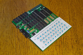
I would like to announce that the Minstrel Issue 3 is finally complete and available to order now.

This is a newly designed, ZX81 compatible 8 bit computer. Ever since I released the Minstrel Issue 2, which was a clone of the ZX80, I have wanted to extend this to be ZX81 compatible. This is Version 3.5, it's taken four previous revisions (and rework in between) to get to this point. I'll go through this in more detail in a later post, covering what went on with each of these and all the stages I went through.
The main change between the ZX80 and the ZX81 was integration of all the logic into a single ULA chip. I couldn't replicate that, so I am sticking with discrete logic chips. As well as this, they solved one of the main problems with the ZX80. The way it was designed, it could either draw the screen, or run user code, it couldn't do both at the same time. See the previous blog post for more about How the ZX80 Works).
The ZX81 added a mode where it could run a small amount of user code in between reaching the end of drawing one frame of video and starting the next. There isn't much time to run the for code, so it is quite slow, hence this is slow mode. The ZX81 could also switch to fast mode, where it acted like the ZX80 and could run the code at full speed at the expense of not showing a screen. Adding this deviates from the ZX80 design, and once I was freed from trying to stick to the original design, I didn't just want to add this mode, I wanted to make this as good a computer as I could. I give myself a list of requirements.

  1. To be able to run 3D Monster Maze
  2. Add NMI based Slow mode
  3. Expand to 32K RAM
  4. Support Hi Resolution graphics
  5. Improve the composite video output
  6. Reduce chip count
  7. Remove dependence on analogue elements
  8. Replace some of the more esoteric logic chips with more common ones
  9. Switch to 74HC series chip
  10. Keep the ZX81 form factor
  11. Keep using only modern still in production through hole parts
  12. Expand the userguide to include full schematics and descriptions of functionality

This took quite a bit of work, but all things have been achieved with the Version 3.5 board. Slow mode has been added, along with a jumper to disable it if you want to run as a ZX80. The RAM has been expanded to 32K, which sits from 8K-40K, mirrored in the top 16K for display file use. The video has been improved with a digitally timed backporch and uniformly sized pixels. I managed to get rid of chips like the 74LS05, 74LS93 and 74LS365, replacing those with more common parts. With all the new functionality, the chip count is now 25 chips, only four more than the Minstrel issue Two. (the original Minstrel Issue 2 will still continue to be available for those who want a pure ZX80 design).
The board powers up to the familiar inverse K prompt, and you can program in BASIC, and of course the first program has to be 10 PRINT something, 20 GOTO 10.
Here you can see another difference with the Minstrel, there is now a border. This was something I added during development, and was useful in describing how the machines work.
 I liked it, so have left it in, as a jumper configurable option.
The jumpers along the front allow slow mode to be disabled (for ZX80 mode), black on white / white on black text, the border colour and 50Hz/60Hz refresh rate for PAL/NTSC regions.
The Minstrel Issue 3 can now run any* ZX81 or TS1000 software (or indeed 4K or 8K ZX80 if you like).
I was also keen to allow it to run various games and demonstrations that make use of high resolution graphics on the ZX81, such as the 25th Anniversary demo.
Vintage high res games, such as the 1980s version of Manic Miner.
How about a test card?
And also new games with impressive graphics, such as Against the Elements by Paul Farrow (yes, these are all running on a bunch of CMOS logic chips and a Z80).
The Minstrel Issue 3 board is the same form factor as the ZX81, so you can use this as a superior replacement for a dead ZX81. The current consumption of the board is around 60mA, so no heatsink is required on the 7805 any more.
The board screws in from the back into the ZX81 case as per the original, and you now have a working ZX81 again, but with the advantage of 32K internal RAM, composite video output, high resolution graphics support etc.
As before, you can also use this as a standalone new build using a ZX81 membrane on a perspex baseplate.
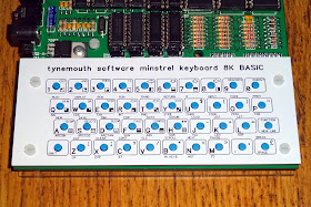
Or I prefer to use the Minstrel tactile switch keyboard with the recently added overlay PCBs.
These allow you to see all the symbols and keywords around each key.
The Minstrel Issue 3 is available to order now from My Tindie Store, either as a PCB, as a kit.
Or if you don't want the fun of building it yourself, I can build and test it for you.
Such a lot of work went into this that there is so much more to tell you about how the design evolved and the decisions made along the way. That blog post will follow next week.
But for the mean time, I think I'll play a little more 3D Monster Maze, or maybe Tut-Tut which was recently released by David Stephenson (a soon to be Minstrel 3 owner).
A final note is the Minstrel Issue 2, the ZX80 version is still available, and will continue to be available for those wanting the full ZX80 experience.

UPDATES:

The Minstrel ZXpand is now available. This is an SD card disk drive designed to work with the Minstrel 3.


 *At least it runs all the ZX81 software I have tried. It doesn't support things like chroma or UDGs that required additional plug in boards, but does support WRX and psuedo high res that will run on a ZX81 with the correct RAM configurations and /WR pulled high. If you have anything you would like me to test, let me know.

2022 Update: At the time of writing, there are still a few Minstrel 2 (ZX80) and Minstrel 3 (ZX81) kits available from  The Future Was 8 bit but those are the Final Edition kits, there are unlikely to be any more at TFW8b.

2023 Update: Minstrel 2, 3 and 4th PCBs, kits and built and tested boards are available via my SellMyRetro store - https://www.sellmyretro.com/store/tynemouth-software

See this post for more information - http://blog.tynemouthsoftware.co.uk/2023/08/minstrel-3-pcbs-kits-and-built-boards.html

Sunday 3 November 2019

Atari 2600 Junior with discrete modulator AV Out Mod

This is an old post, preserved for reference.
The products and services mentioned within are no longer available.

Here is another Atari 2600 Junior ready for a composite video output modification.
This one is a little different, in that it does not have a modulator inside a metal can like most other 2600 boards.
Normally that section has a metal can UM1233 (or equivalent) modulator.
There is not much information about a composite video conversion on this type of board, so I thought I would go through my process for working out which parts to remove, and where to tap the necessary signals.
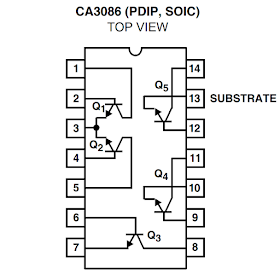
There is one IC in the modulator section, uA3086PC, which I initially thought would be an RF modulator chip, but when I looked around, it turned out to be a transistor array.
So basically five transistors in an IC package, two of which are matched and arranged with a common emitter to form a long tail pair. Looking at the schematic of the 2600 Junior, these are drawn as discrete transistors inside a box.
There is a lot going on there, so here is a simplified version, which can be applied to most the 2600 systems I have seen. (the exception being the four switch 2600s where they tried to cut costs by removing the 4050 buffers, the picture quality suffered and they were back in the 2600 Jr). Various parts have been omitted for clarity, mainly pullup resistors.
Here you can see the TIA chip has three luminance outputs, a composite sync output, a colour burst and finally an audio output. The luminance and sync outputs are buffered via 4050 gates before being merged with the colour burst signal. An audio subcarrier oscillator is applied to the audio signal from the TIA and is also merged at this point to give composite video and audio which is then modulated by the RF oscillator to generate the UHF TV signal. (OK, that's very generalised, but you get the basic principle).
In order to get clean composite video and separate audio, these elements need to be separated, which can be done without cutting any tracks, just by removing a couple of components. There is normally an 18K resistor connecting the decoupled audio signal from the audio subcarrier oscillator, so removing that detaches the audio signal. It is best to pick this up after the decoupling capacitor to protect the TIA. The modulated audio is usually connected to the composite video signal via a 1K8 resistor, so removing that again separates the two. The final task is to disable the two oscillators to save power and reduce noise. Usually accomplished by removing the transistors and power feed.
On the actual schematic, you can see the parts highlighted to be removed. R48 disconnects the audio.  Removing Q4 will stop the audio subcarrier oscillator. I would normally also remove the variable inductor that powers the oscillator (which is normally the tall red coil), but in this case L8 is in a metal can which would be a little more effort to remove, so I have gone for the two polystyrene 820pF capacitors (C53,C54) instead.  Removing the transistor array chip is one way to disable the RF oscillator, but it is easier to remove a few passive components instead. Removing the transistor next to the IC (Q3) disconnects power from the rest of the transistors, so that should stop it oscillating, and R17 and C33 disconnect that from the signals.
The following parts were removed: Q3, Q4, R17, R48, R56, C33, C53, C54.
For a neat modification, I am using the Future Was 8 bit Deluxe Composite Video mod kit (currently on offer at £10).
The board mounts at the back where the RF output jack used to sit. Raised up on a couple of foam pads.
The four wires are connected to composite video (yellow), audio (white), power (red) and ground (black). There are usually several suitable points to connect each one to. I normally choose the closest or neatest to wire.
Power can be tapped from a via above the removed C33 which carries a clean 5V supply, and ground and composite video can be tapped from the pads of C33. The audio is tapped from the top of R48.
As ever with these things, keep the wires short. We supply the kits with a good length of cable to allow installation is as many devices as possible, but generally, the wires should be cut short, and kept out of the way of any of the digital ICs.
Another example is this 4 switch 2600, the board is positioned with nice short cables, and so that the supplied AV lead can run out the case through the same hole the original RF lead did. See my previous post on Atari 2600 Composite Video Mods for more examples, including the metal can modulator version of the 2600 Junior.
This 2600 is all done and ready to go back into it's case.