Showing posts with label AY-3-8912. Show all posts

Saturday, 21 January 2023

Driving the AY-3-8910 / YM2149 from an 8 bit micro

In several previous posts, I have been building and using the RC2014 YM2149 sound card from Z80kits.com.

In the last post, I glossed over a strange anomaly in the way these devices are driven from the Z80 bus. It all goes back to the original use of the General Instruments AY-3-8910 chip, which was with the early General Instruments PIC microcontrollers like the PIC1650, or the General Instruments CP1610 microprocessor (as used in the Intellivision console).

Most other chips used on 8 bit microcprocessor systems in the day were designed for things like the 65xx/68xx series or the 8080/Z80 series, and as such use a separate data bus and address bus. Interfacing to these is fairly straightforward.

65xx/68xx series

These microcprocessors have an 8 bit data bus and usually a 16 bit address bus. IO is memory mapped, and everything is controlled from a single R/W pin, high for reads, low for writes.

There are two states for accessing external devices:

R /W
State
0
Write to external device
1
Read from external device

Z80/8080 series

These microcprocessors also have an 8 bit data bus and usually a 16 bit address bus. IO and memory are accessed separately with either a /IO_Request or /Memory_Request signal, and there are separate /Red and /Write signals.

As well as various other modes for interrupts etc., there are four states for accessing external devices:

/Read
/Write
/IO Request
/Memory Request
State
0
1
0
1
Read from external IO device
0
1
1
0
Read from external memory device
1
0
0
1
Write to external IO device
1
0
1
0
Write to external memory device

/WR and /RD both low is invalid, both high is inactive. /IORQ and /MEMRQ low is invalid, both high is inactive.

CP1610

These microprocessors have a combined 16 bit address and data bus, and these are controlled by a BusDirection signal (BDIR) and two BusControl lines (BC1, BC2).

There are eight states used on those systems, but for simplicity, I will only look at the four used by the AY-3-8910.
BDIR
BC2
BC1
State
0
1
0
Inactive
0
1
1
Read from external device
1
1
0
Write to external device
1
1
1
Latch Address

BC2 is always high in these situations, so can be pulled high or wired direct to 5V as it is in all of the circuits below. There are also two additional address lines, A8 and /A9 (only on the 40 pin chip), these are not used in these applications, and just pulled high and low respectively.

As a side note, look at that pinout. See if you can spot D0 and D1. Why couldn't they just put them in order. It's like the databus on a Z80, that is just annoying.

How do other computers do it?

These signals don't easily map to those used on the Z80 or the 6502, and looking at machines from the 1980s, various methods were employed to get around this.

Amstrad CPC464

To get around the complications of driving these pins directly, the Amstrad CPC464 uses an 8 bit IO port on an 8255 PIO chip to drive the data bus, and two lines from a second port to drive BDIR and BC1.

This also avoids any issues of the speed of the bus interface (which seems to vary from datasheet to datasheet), since the data can be latched on the IO chips output port for as long as necessary and the BC1 and BDIR singals toggled before and after setting it.

This may seem wasteful of an IO port, but the AY-3-8192 chip used has it's own 8 port which is used to drive the keyboard and joystick. Slightly convoluted, but it works.

Oric 1 / Atmos

The Oric solution is very similar. A port on the 6522 VIA is used to drive the databus, which is shared with the printer port. Two of the handshaking pins on the 6522 drive BC1 and BDIR.

The Oric 1 PCB has a direct connection from CB2 to BDIR, but some Atmos boards had the track cut and a 1nF capacitor installed, which would delay the BDIR pulse slightly. As seen on a previous repair blog:

http://blog.tynemouthsoftware.co.uk/2022/11/oric-atmos-repair.html

The IO port on the AY-3-8192 is used to drive the keyboard.

The Oric is the only one to directly tie the three outputs together, the rest use a resistor mixer to combine the three output channels.

ZX Spectrum + / +2

The ZX Spectrum + and +2 drive the data bus direct, but the BC1 and BDIR are driven by a combination of diodes and resistors, redrawn below. The IO port is used to drive the 1488/1489 buffers that form the keypad and serial ports.

If the PSG (Programmable Sound Generator) line is low, BC1 and BDIR will be pulled low via the diodes, leaving the chip in the inactive state. If that is high, the diodes do not conduct, and the two pins are driven via resistors. BDIR is driven from /RD, and BC1 is driven from A15.

Connecting the AY-3-8910 to the RC2014 bus

The RC2014 YM2194 / AY3-8192 sound card also uses a direct bus connection, but the generation of the control signals is more complicated. I've redrawn that to work it out, with the jumpers set in their default positions. The board can be jumpered for various other combinations (including ZX Spectrum mode), but I have drawn it in the "default" mode. I have shown the 28 pin AY-3-8192 as I had that drawn already. The board actually uses the 40 pin AY-3-8190 which just has an extra 8 bit IO port, but as seen in a previous post, you can use an AY-3-8192 in an adapter socket.

The first 74HCT138 is used to decode addresses in the range D0-DF, shown as /Dx, inverted to give Dx.

The second 138 is enabled when the current address is in the Dx range, A1 is low (so D0, D1, D4, D5, D8, D9, DC, DD) and an IO Request is in operation. This is further filtered by the three address inputs. Three outputs are generated, /D8_Read, /D0_Write and /D8_Write. These are combined by the two 74HCT00 NAND gates to give one signal which is high when there is a D8_Read or a D8_Write; this drives BC1. The second signal is high when there is a D8_Write or a D0_Write; this drives BDIR.

That gives the following results:

Signal
BDIR
BC2
BC1
State
-
0
1
0
Inactive
D8 read
0
1
1
Read from external device
D0 write
1
1
0
Write to external device
D8 write
1
1
1
Latch Address

As you can see, that's not quite what you would expect. D0 (also D1, D4 and D5) is the data register. Writing there is a write to the sound chip, that's OK.

D8 is the address latch (also D9, DC and DD). Writing there latches the address.

However, the read operation is set for D8, so to read from the chip, you read from the register port rather than the data port. I am not sure if there is a specific reason for this, maybe compatibility with some existing systems? (and no, you can't change that with the jumpers)

The D0 and D8 addresses in hex are the 208 and 216 addresses in decimal in the previous posts.

The full schematic for this V5 version of the board can be found on the designers github:

https://github.com/electrified/rc2014-ym2149/tree/4b8af5396633bc87178b81087cec0f71b8307908

Note there is also a V6 version of the board which removes the D0/D8 access and uses addressing compatible with the Spectrum and MSX:

https://github.com/electrified/rc2014-ym2149

Could it be fixed?

Swapping the output of the second 138 from pin 12 to pin 13 should make it respond to reads on the data port instead.

I guess the existing board has been around long enough now that reading the register port is the accepted way of doing it, and to change it would break existing code.


Advertisements

Minstrel 4D

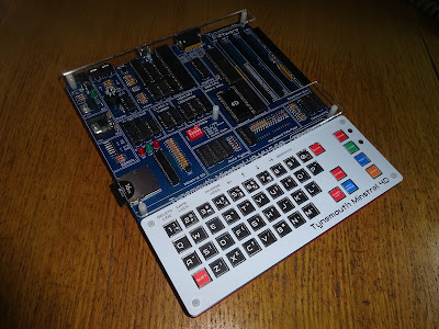
The Minstrel 4D kits are shipping now, you can order one from The Future Was 8 bit

https://www.thefuturewas8bit.com/minstrel4d.html

More info in a previous post:

http://blog.tynemouthsoftware.co.uk/2022/08/minstrel-4d-overview.html

Z80 Kits

The YM2149 Sound Card is available from Z80Kits.com

https://z80kits.com/shop/ym2149-sound-card/


Patreon

You can support me via Patreon, and get access to advance previews and behind the scenes updates. These are often in more detail than I can fit in here, this post contains bits from three Patreon posts, and there is a forth and fifth to follow. This also includes access to my Patreon only Discord server for even more regular updates.

https://www.patreon.com/tynemouthsoftware
Sunday, 8 January 2023

Testing the AY-3-8910 / YM2149 Sound Card for RC2014 (and Minstrel 4D)

In a previous post, I built an AY-3-8910 / YM2149 Sound Card for RC2014 (and Minstrel 4D)

In that post, I tested the card using the game Valkyr, which has built in support for a similar device, and has been patched to use this card.

Today, I want to try a few more things, and also look at some of the other supported chips and some of the potential problems associated with sourcing them.

Play

George Beckett has a repository of Forth programs which support this card (including the aforementioned patched version of Valkyr). https://github.com/markgbeckett/jupiter_ace

One of those is "play", which can be used to play a series of notes, given by their letters (c, d, e, etc.) with # and & for sharps and flats.

A special version has been provided for the Minstrel 4D. Unlike the original, this has Forth and assmembly in a single dictionary ("playd"). This can be loaded from the SD card menu on the Minstrel 4D. Note here the menu scans the file for a dictionary and identifies it is called "play", even though the file is called playd.TAP.

Select option 2 to load it (we don't want to run "play" directly, so we don't use the first option).

I am still pleased with the loading lines on the Minstrel 4D. For those not in the know, the Jupiter Ace didn't do that, you just has to sit and wait and hope the program loaded.

Once that is loaded, you can use it to create words that will play tunes (see the notes on George's page for more info).

Typing over serial is really useful for this sort of thing, you can just select the text from github and paste it into a terminal window and have it typed into the 4D automatically. You can then save if to SD if you wish to enjoy Hall of the Mountain King at a later date. Or you can add it to your own program and have it playing over the title screen (see notes about relocatable code if you do).

Audio Output

These chips are three channel, mixed down to two for a stereo output. The YM2149 seems to suit the mixer on the board better, compare the tune from the start of Valkyr.

On the AY-3-8192, there is more bleed through.

You can also see that during the gameplay. There look to be three types of sounds, one on each channel, you can see that more clearly on the Yamaha chips.

The laser firing noises are on channel 3, which is mixed equally to left and right, and different ship and explosion noises are on channel 1 and 2 (left and right).

On the AY-3 chip it seems a bit more jumbled up.

Either way, it enhances the game play.

Sourcing chips

This card supports a variety of different, but largely compatible chips. Unfortunately, none of those are still in production, so you have to rely on the likes of ebay, and as I am sure you are aware, all may not be as it seems.

Here I initially assembled four chips to test. These are as follows:

  • GI AY-3-8910A, datecode 8547
  • Yamaha YM2149F, datecode 8903
  • Microchip AY-3-8910, datecode 0827
  • Microchip AY-3-8910A, datecode 1030

I have had the GI and Yamaha chips for a long time, and I have no reason to think that they are not genuine chips.

The "Microchip" ones, less so, these are from ebay. I have not been able to find a date when they stopped making these, but I suspect they are both dated a bit late. I'm not entirely sure if Microchip only produced their improved AY-3-8930 / AY8930, or if they did actually produce Microchip branded AY-3-8910 and AY-3-8910A chips.

Just based on the packaging, with the two release marks, the dot for pin 1 and no notch, I think the Microchip AY-3-8910 dated 0827 is in fact a Yamaha YM2149F. It has gone through an unfortunate process where it has been sanded down, painted black and laser etched to look like a Microchip device.

This is confirmed by the first test, which is the output level. The original Yamaha device outputs sit at about 2V at rest, and the 0827 Microchip matches that.

The other Microchip chip looks and acts like the AY3-8910, with a notch for pin 1, and there are two release marks and a dot for pin 1 which are still just visible, the result of the chip being sanded down.

Comparing it to the original GI chip and a contemporary Microchip PIC, it is clear the font and logo are wrong, but the release holes don't quite match either of the other chips. It does however have a low output, around the 0.2V expected from the GI chips. So it looks like the 1030 Microchip is actually an AY-3-8910A, just remarked with a later date.


Register test

There is another way to tell. Some of the control registers are not fully used. Register 0 and 1 together provide a 12 bit tone period. Register 0 uses all 8 bit, but register 1 uses only 4 bits. In theory, the GI chips will always return 0 for the unused bits, but the Yamaha chips will store and return all the bits written, even though they are not being used.

In this test program, I am selecting a register, writing 0 and reading back and displaying the value, then writing 255 and reading and displaying that.

First off, select register 0, write 0, read 0. Good start.

Write 255, read 255, as expected.

OK, so that is working.

Now it is time for register 1 (which is only 4 bits).

Select register 1, write 0 and read 0, so far so good.

Write 255 and read 15.

Ah, so that would suggest this is an AY chip, as it has read 0 for the upper 4 bits, and the value written for the lower bits.

I did have a long section here about how the unusual interface to these sound chips works, but this post is already way too long and I am barely half way through, so I will move that to a separate post -

http://blog.tynemouthsoftware.co.uk/2023/01/driving-ay-3-8910-ym2149-from-8-bit.html

Briefly then, most of the other chips used in the 8 bit era were designed for the 65 or 68 series chips or the 8080/Z80, but these were designed to be used with the more obscure GI CP1600 and early GI  PIC microcontrollers (before the Microchip takeover of GI, and before the Atmel takeover of Microchip).

These had a shared address and data bus, hence the odd way you have to select the register then write the data. On the CPC464 and Oric, the chip is connected to the outputs of an IO chip, rather than direct to the databus, to be able to drive this. On the Spectrum +2, it is driven from a latch forming a simple output port. On this RC2014 card, it is being driven direct, so there are a few oddities, like reading data back via the register port.

OK, time to test the other three chips. I expect to get 255 for both registers.

Well, that is what I expected, unfortunately, I also got 15 for both the (theoretically) Yamaha chips.

Not sure what is going on there.

At this point, I was doing a lot of powering on and off (soft power on is great, isn't it?), and swapping chips, so I had fitted a ZIF socket to the board to make that easier.

I was making changes to the code in a text editor and pasting the text over serial to the Minstrel 4D. When doing that a lot, it is useful to disable the menu at power on, so it boots straight into Forth, ready to type in the code. Go to settings, and press A to disable it.

You can still get to the menu by pressing the Menu button, and then go to settings and turn it back on by pressing A again when you're finished.

I reached out to Ed Brindley, who designed the RC2014 card, and he also expected to see different results from the Yamaha chips. However, he also ran some tests and seem to confirm the results I was getting, 15 way being read back, from all the chips.

He was testing all registers, so I wrote some more forth to test all 16 registers. ("YM2149" and "Real" are printed at the start to make it easier to know which results are which, I changed that to match the chip being tested).

216 CONSTANT REGPORT
208 CONSTANT DATPORT

: REGS
  CLS
  ." YM2149" CR
  ." Real" CR
  CR

  16 0
  DO
    I .
    I 10 < IF ."  " THEN
    I REGPORT OUT
    255 DATPORT OUT
    I REGPORT OUT
    REGPORT IN .
    CR
  LOOP
  CR
;       

(is there any interest in going into a bit more detail of the Forth used here, line by line, for those new to the language?)

All these test programs on here are available on my github - https://github.com/tynemouthsoftware/Forth.

I ran this with a real YM2149 and the results were as before, only the allocated bits were returned, the rest were 0.

I repeated that on each of the types of chips I had, and the results were all exactly the same on every chip.

I also added an AY-3-8192 to that test, using the adapter board that came with the kit from Z80kits.com.

Now it is of course possible that all my chips are actually AY-3-8910, some of which have been remarked as YM2149, but that seems unlikely.

More chips to test

To be sure, I dug around in my spare boards to find some more chips.

First up, another AY-3-8912A, this one from a dead ZX Spectrum +2.

I found a couple of scrap boards with YM2149 chips on, one from an Atari ST.

And one from an MSX.

Do you spot anything about the MSX board?

Yes, the position is marked for an 8910, but the Yamaha YM2149 is fitted instead. It also has the full part number on the back.

The MSX board had already been raided for parts, so I desoldered the YM2149 from there.

Both of these chips were factory soldered to boards in the 1980s, so I have no reason to think that they are not real chips.

OK, as expected, the AY-3-8192 returns 15 for register 1, only the used bits.

Oh, so does the YM2149.

OK, so that seems to confirm that this "reading back extra bits" thing doesn't work.

I fed this back to Ed, who did a bit more digging, and it turns out that the behaviour is different if you write 31 rather than 255 to the port.

So I tried writing 31 instead, and got 31 back.

I didn't take a screenshot, I just updated my test program and ran that and it worked!

I ran the same test on an AY-3- 8910 and that was also correctly detected.

So the information about the extra bits was correct, just with a caveat. If you write 31 to register 1, you will get 31 back on a Yamaha YM2149, and 15 back on an AY-3-8910/2. All other bits and values work the same on both devices. Excellent, we have a test program.

216 CONSTANT REGPORT
208 CONSTANT DATPORT

: DETECT
  CLS
  1 REGPORT OUT
  31 DATPORT OUT
  REGPORT IN 31 < 
  IF ." AY-3-8910/2"
  ELSE ." YM2149" 
  THEN
  ."  Detected"
  CR
  CR
;       

Conclusion

After all that, and testing many different chips, I can confirm that at least with these particular chips, all the chips with the notch on the end were AY-3-8910, and the ones without the notch were all YM2149, despite what the marking say.

Yamaha YM2149 chips

I believe all three of these are Yamaha YM2149 chips.

  • The package has a round depression for pin 1, and no notch on the end
  • The audio outputs have around 2V offset voltage
  • When you write 31 to register 1, you read 31 back

It seems both of these chips started out life looking pretty similar. You can sort of see why they would do the remarking. The old, scratched, chip with the less popular part number, and older date code is far less likely to sell than the one that has been sanded, painted, and laser etched with a largely compatible, more popular part number, and a more recent date code.

Whoever is doing this, please stop it.

AY-3-8910/2 chips

I believe all of these are GI AY-3-8910 and 8912 chips.

  • The package has a round depression for pin 1, and a notch on the end
  • The audio outputs have around 0V offset voltage
  • When you write 31 to register 1, you read 15 back

It is not clear if the two chips remarked as Microchip were originally Microchip, or were old GI chips like the rest.

You can just see the remains of the pin 1 dot in the right light. Not much left after the original top later has been sanded down.

If you don't believe me about the sanding, see for example this AT28C64B chip where not all of the original top was sanded off before it was remarked.

See this video for much more information about the remarking of chips: https://www.youtube.com/watch?v=k72SFBOZ_lw


Conclusion to the conclusion

So, after all of that, which chip am I leaving in the board?

Well, the Yamaha YM2149 seems to sound better to me. I am using the old scratch one, I just gave it a bit of a clean up with some Meguiar's Plast-RX, which is good at getting out light surface scratches, and it turned out reasonably presentable.

I think that is all I have to say on this for the moment, that turned out to be a lot more than expected, I hope you found it interesting.

Thanks to George Beckett and Ed Brindley for their help with this post


Advertisements

Minstrel 4D

The Minstrel 4D kits are shipping now, you can order one from The Future Was 8 bit

https://www.thefuturewas8bit.com/minstrel4d.html

More info in a previous post:

http://blog.tynemouthsoftware.co.uk/2022/08/minstrel-4d-overview.html


Z80 Kits

The YM2149 Sound Card is available from Z80Kits.com

https://z80kits.com/shop/ym2149-sound-card/


Patreon

You can support me via Patreon, and get access to advance previews and behind the scenes updates. These are often in more detail than I can fit in here, this post contains bits from three Patreon posts, and there is a forth and fifth to follow. This also includes access to my Patreon only Discord server for even more regular updates.

https://www.patreon.com/tynemouthsoftware