
The third Mini VIC development log. Lots of clock talk in this one from February 2022.
I need to address one of the points I glossed over in the list of things to do in the previous post. I am cheating a bit with a 4MHz dot clock. The VIC20 used something close to 4MHz, but the actual value is based on the video circuitry, and is generated by the VIC chip. This PAL VIC20 CR uses a 4.433618MHz crystal to generate the dot clock and it is divided down to get the CPU clock.

This is different between PAL and NTSC systems, and between the PAL 2 pin VIC 20 and the PAL 7 pin VIC20 CR. In all three different crystals were used in VIC20 systems.

I've shown the frequencies in terms of multiples of the CPU clock as that makes it a bit easier to see what is going on, although in practice everything is divided down from the crystal frequency rather than being multiplied up.

I have covered the differences between the three models, and conversions between them in previous posts, and also one on a multi region TED machine if you fancy that as well.
- http://blog.tynemouthsoftware.co.uk/2016/08/vic20-pal-to-ntsc-conversion.html
- http://blog.tynemouthsoftware.co.uk/2017/12/commodore-vic20-2pin-pal-vs-ntsc.html
- http://blog.tynemouthsoftware.co.uk/2020/04/commodore-16-pal-to-ntsc-switchable.html
The microcontroller runs at up to 16Mhz, and it would be a lot easier if this were a multiple of the final dot clock and CPU clock I am looking to achieve.
Using the 16MHz timings for simplicity, one horizontal line of character on the VIC20 screen is 2us long. That is, the video signal wiggles up and down for 2us in a pattern of highs and lows that are turned into blue or white pixels on the screen.

These patterns are generated by clocking 8 bits of data out of the shift register with a clock that runs at 4MHz.

If the microcontroller ran at that same 4MHz, it will have just 8 instructions to fetch the next character from the memory and look up in the font ROM what pattern of bits it needs for the current line of that character, and load this into the shift register just in time for the next character.
That's a tall order in 8 cycles. If the microcontroller runs 4x faster at 16MHz, it will then have 4x as many cycles to achieve that task. 32 instruction cycles is still not many, but it should be enough. (I am glossing over at this time that it also needs to look up the colour, allow half of those cycles for the CPU to access the memory, and also check if the CPU has read from or written to any of the VICs internal registers - but lets leave that for the moment)
I have worked out two options for the microcontroller clock. One is 16x the CPU clock, the other is 14x the CPU clock.
The 16x CPU clock is 4x the dot clock. That matches the 1MHz / 4MHz / 16MHz ratio on my current test board. The 14X CPU clock is 3.5x the dot clock, the same ratio as the NTSC VIC20.
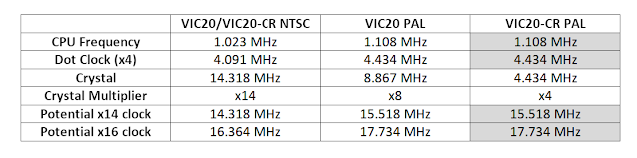
The x14 option gives 14.318 MHz and 15.518 MHz, which are both clear of the 16MHz limit, but give only 28 cycles per character, rather than 32. Not sure at this point how many of those I am going to need.
The 16x options gives a 16.364MHz / 17.734MHz clock for the AVR, which is a bit high for the chips rated at 16MHz. It's only 10% over, but is that too much of an overclock?

They quote voltages in terms of 4.5-5.5V (5V +/- 10%), but the tolerance of the maximum frequency is not given. If you external clock is 16MHz +/- 1% that could mean 16.160Mhz, which is also over 16MHz, but is that OK? Not sure
Why use those particular frequencies anyway?
Those odd frequencies are related to the colour burst frequency in the composite video signals.
Generating those it a bit complicated. There are chips which will do it, such as the LM1889 used on the ZX Spectrum and elsewhere - well out of production. The only one still in production (but out of stock obviously) is the AD724JR used on the Harlequin Spectrum clones. (Note the crystal is marked 4.433619MHz not 4.433618MHz as in the VIC20. It should be 4.43361875 MHz, so I guess the rounding on this crystal is more correct)

I am considering not bothering with colour composite video and just having black and white composite and RGB monitor or SCART connection, but I would still like the CPU to run at the original speed if possible.
I am not sure how best to deal with those different speeds to offer PAL and NTSC, maybe two external crystals or possibly one of those PLL chips which can generate any clock speed from a base crystal?

This is the SI5351, and it looks promising. It is programmed over I2C and generates three clock outputs at any frequency from 8 kHz to 160 MHz, including fractional values such as the ones I need.
It's a 3.3V chip, so the inputs and outputs are 3.3V. This (clone of an) Adafruit module includes a 3.3V regulator and level shifters for the I2C inputs (but not the outputs which will need separate buffers).
The calculations are a bit involved, I have worked out four sets (PAL and NTSC versions of 16x and 14x clocks). There is a program to help, but you still have to do quite a bit of juggling to get the best results.

The ratios are not shown there, but are calculated as follows:
NTSC = 315/88 = 3.57954545455
14.318181818 = 315/88 * 4
4.090909091 = 315/88 * 16/14 = 14.318181818 / 3.5
1.022727273 = 315/88 * 4/14 = 4.090909091 / 4
Here I am starting with the NTSC frequency as 315/88 which is the actual definition of the frequency in MHz, rather than just using rounding to a few decimal places, so it has lots of precision.
Internally, the chip starts with a 25MHz crystal, multiplies it up to a high common factor, then divides it down to get the final value.
25 MHz * 36 = 900 MHz
900 MHz / 880 = 1.02272727273 MHz
I don't know at this stage if I will need the divided down versions, or just the ~16MHz microcontroller clock.
The values here aren't exactly right, I'm not sure about the accuracy of the logic analyser, it's resolution isn't great at higher frequencies (even at 200MHz sampling).

For the moment I will leave it at 4MHz dot clock and 1MHz CPU clock and deal with the specific timings later.
The last point on this subject (I promise) is the alternate microcontroller choices. I am still considering the AVR128DA/DB range, it's going to take more work to get up to speed writing code for them, but the 24MHz clock would give me 48 instruction cycles per character rather than 32, which I might need. The Dx range also has an improved AVR core and some of the 2 cycle instructions in the old older ATmega range are now single cycle, including crucially SBI and CBI which set or clear an individual IO pin. That would also be helpful in squeezing as much into the 2us character window.

There is a bit of inconsistency in the datasheet. In several places it seems to imply these chips can use an external clock up to 32MHz, but it others it says the maximum is 24MHz.

The Atmel Start page won't accept values over 24MHz, yes it has a dropdown to select up to 32MHz external crystal (and there are matching bits in the register it sets). It seems it may be possible to use an external crystal oscillator at 32MHz, which would give me a luxurious 64 instruction cycles per character.

I have raised a support case with Microchip to see if they can confirm if 32MHz is supported. I have ordered some oscillator modules just in case, but I don't want to try it out in case I am overclocking the chip and fry it.

I'll call this one Bob.
2023 Update - it turns out you can use up to 32MHz crystal, but only if it is configured to be divided down to below 24MHz, which doesn't help here.
The rest of this post is a mini rant, feel free to switch off now (if you haven't already).
I had to straighten three of the four pins on these modules, they arrived in individual plastic tubs. Good old RS, they love their excessive packaging.

Bob came a clear tub like that one, rattling around with no protection on the pins. I also ordered a surface mount version (above) in case it worked and I wanted to solder one directly to the module.

As much as I complain about RS, they do give me free next day delivery and no minimum order charges. I feel bad about ordering just a few pounds worth of parts and still getting free shipping. I often add more items to the cart to bring the value up, and then realise I have wasted my time when the end up getting shipped separately anyway.
Even though more than half of the listed items are out of stock, they have still not implemented an "out of stock" filter. I ended up having to check thirty or forty listing for 32MHz oscillators until I found one that ran at 5V and was in stock.
When I was there, I was amazed to see that the AVR128DB48 was in stock, so I thought I would add some to the order (in case I fried the one on the red board, or in case I made a PCB for this project later on).

So overjoyed to see a microcontroller in stock, I ordered some, and they arrived the next day.

Yes folks, I didn't see that they had listed the VQFN (nasty tiny square things with no legs) with a picture of the nice friendly TQFP chip.
Rant over.
Advertisements
Minstrel 4D
No Mini VIC kits any time soon, but the Minstrel 4D kits are shipping now, you can order one from The Future Was 8 bit - SPECIAL OFFER - £15 off the Minstrel 4D and free shipping to the USA
https://www.thefuturewas8bit.com/minstrel4d.html
More info in a previous post:
http://blog.tynemouthsoftware.co.uk/2022/08/minstrel-4d-overview.html

Patreon
You can support me via Patreon, and get access to advance previews of posts like this and behind the scenes updates. These are often in more detail than I can fit in here, and some of these posts contain bits from several Patreon posts. This also includes access to my Patreon only Discord server for even more regular updates.
https://www.patreon.com/tynemouthsoftware


