
This is a revised and updated version of a Patreon only post from 2020 about a project from 2016 that I might be bringing back in 2024.
Way back in 2016, I designed a board to add 128K paged RAM to a Commodore PET.

It was very much a 'because I can' type project. Not really that much use. The Commodore 8096 / 8296 had an extra 64K paged RAM implemented in the same way. The 6502 can only address 64K, half of which is RAM in the PET, the rest is video RAM, IO and ROM.
These board use paging to add extra RAM, so that is not accessible to BASIC (it lives behind the BASIC ROMs for a start). The machine would only ever report the standard 31743 bytes free, not 97279 as you might hope.

Only specially written machine code programs could make use of the extra RAM. I found a few test programs, a German office suite, an OS extension LOS-96, and a modern version the Infocom Z-machine interpreter (https://petsd.net/petfood.php?lang=en), but nothing else would make use of it.

This was Commodore's version, a 64K RAM board which could be added to an 8032 / 8032-SK to make an 8096 / 8096-SK. In practice, it would just sit there burning about 10 watts of power, with the ever-present threat of 4116 failure. Normally the best thing you can do is unplug them and revert the machine to a more reliable standard 32K machine.

The 64K on there is made up of 32 x 4116 chips, so as you can imagine, all of the 64K RAM boards I have ever seen have had bad chips.
I don't think this one is going to work.

These were controlled by an unusual intel D3243 refresh controller.

The rest of the board is taken up with the logic that controls the RAM board paging.

That board was mounted on top of the standard 8032 board to make an 8096, or in the top of the case on an 8032-SK to make an 8096-SK.

The functionality was later integrated into the mainboard of the 8296 (and 8296D), albeit implemented very differently.
I did find a 1980s third party version in a PET that came in for repair. That was less than half the size.

This was essentially the same, but used 4164 chips, so was less power hungry and maybe a little more reliable.

It looks like it also has space for up to four expansion ROMs.

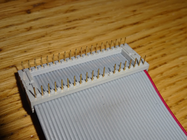
Like the Commodore board, this plugs into the 6502 socket on the PET via a ribbon cable. Although it looks like it is damaged, these all have pin 8 (5V) disconnected and generate their own 5V on board.
I designed a replacement using two GAL chips and a single 128K RAM chip that would plug directly into the 6502 socket, like the PET ROM/RAM does.

There were also two logic chips, a 245 buffer and a 273 latch hidden under the other chips, and an LED array to display the status of the control register.

This plugged directly into the 6502 socket on the PET board and should do the same job as the Commodore 64K board, (N.B., that is the 64K RAM board from Commodore, and not a Commodore 64 RAM board).
Thanks to a spare bit in the control register, that should be able to provide a total of 128K of extra (pointless) RAM, not just 64K.

Everything is controlled by a write only register at address $FFF0. The status of that is shown on the LED. It controls two areas of 16K, each of which can be one of two banks (one of four in the 128K version). Also write protect of those areas and 'peek through' to the RAM and I/O address ranges which are in the same area.

The only problem was that it didn't work. The initial problem was the register kept getting reset to the wrong values and locking things up. That turned out to be a timing issue.
At that point I was having lots of issues with the GAL chips I was using. Never got down to what the problem was, I was blaming my equations, the compiler, the programmer, the GAL chips, and tried using various different types of each but kept getting inconsistent results (recompiling the same code would make it work, reprogramming the same chip would break it etc.).

I shelved quite a few GAL projects, including a dual GAL PLA replacement, which also sort of worked, but not consistently with Lattice GALs, or Atmel ones, with various different programmers and all sorts of settings on the WinCUPL compiler. (ed. I notice someone has since done one of these)
Roll forward to 2020 and I have designed the Mini PET and have gone into great detail with the RAM timings getting that working with the modern W65C02 CPUs. I've also now got Microchip produced F22V10C GALs. These should be the same as the Atmel ATF22V10C versions, but Microchip have been slowly dropping the AT prefixes.

Time to have another go at the PET 128K board.

I had to make a few modifications to get it working with the new CPU on the Mini PET, as the pinout and timings aren't the same.

Started off fairly simple, but as usual, got a bit more involved.

I hadn't fully understood the way the PET 64K RAM board disabled the onboard ROM and RAM. It is quite neat really. They disable part of the buffered address bus and four resistors pull the address up to Fxxx (I'm not swearing, I just mean any address from $F000 to $FFFF). The lower 12 bits are unchanged, the important thing is to move the addresses into the range of the KERNAL ROM.

This is used in combination with the /NO_ROM signal, one of the spare pins on the 6502 CPU socket which is used to disable all the ROM chips using a second active high enable line on the mask ROM chips which is normally pulled high.

The upshot of that is, when the expansion RAM board is active, it sets the address to somewhere in the KERNAL ROM $F000-$FFFF. The ROMs are disabled, so nothing on the PET board should be active and the RAM board can act.
I couldn't easily implement that solution, there was nowhere on the 128K board to bodge in a 244 or maybe a 157 to disable the address bus. Also, the Mini PET does not support /NO_ROM as that pin on the W65C02S has been reassigned and is now an output of the CPU.
As an alternative, I have gated the read/write signal. When the RAM should be in use, the PET board always sees a read operation each time, never a write. The 245 buffer disables the databus, so whatever is read is ignored, and nothing gets written to when the expansion RAM is in use.
Let's see if it works.

Success, I could see the test programs were running and the extra RAM was detected by Zork. With the extra RAM it takes three times as long to load, but there will be less disk seeking once you started playing. That would make sense if you have a slow disk drive, but with something like the SD2PET it doesn't make much difference when you are playing the game, but the extra RAM actually makes it worse because of the slower load.
Roll forward to later in 2020 and I updated the PCB design for these changes, now in white to match the Mini PET. But as the "your PCBs are in production" email arrived, I realised there was a problem. (normally at that point I just spot all the typos on the silkscreen, rather than design flaws)

I added a jumper to this version to downgrade it to 64K mode, in case there is some software which does not set the unused bit correctly and might accidentally switch to the alternate 4 banks.

The problem means that it works, but is not ideal in practice. Reads are generally safe, but reading some of the registers in the IO range has two problems, firstly reading some of the timer registers in the 6522 VIA causes the interrupt flag to be reset which may affect software using both timers and paged RAM at exactly those addresses (unlikely but not impossible).
But more importantly, the address decoding on the IO chips in the PET is minimal, so there are multiple ranges of addresses where the IO chips will conflict with each other.
I have borrowed this from a post I am working on about PET address decoding. Five of those 16 addresse ranges are safe, but any of the others would cause a bus conflict if you read or write from RAM mapped into that area, so it needs an alternate solution.
Address |
Binary |
CRTC |
VIA |
PIA#2 |
PIA#1 |
|---|---|---|---|---|---|
E80x |
0000xxxx |
- |
- |
- |
- |
E81x |
0001xxxx |
- |
- |
- |
✔ |
E82x |
0010xxxx |
- |
- |
✔ |
- |
E83x |
0011xxxx |
- |
- |
✘ |
✘ |
E84x |
0100xxxx |
- |
✔ |
- |
- |
E85x |
0101xxxx |
- |
✘ |
- |
✘ |
E86x |
0110xxxx |
- |
✘ |
✘ |
- |
E87x |
0111xxxx |
- |
✘ |
✘ |
✘ |
E88x |
1000xxxx |
✔ |
- |
- |
- |
E89x |
1001xxxx |
✘ |
- |
- |
✘ |
E8Ax |
1010xxxx |
✘ |
- |
✘ |
- |
E8Bx |
1011xxxx |
✘ |
- |
✘ |
✘ |
E8Cx |
1100xxxx |
✘ |
✘ |
- |
- |
E8Dx |
1101xxxx |
✘ |
✘ |
- |
✘ |
E8Ex |
1110xxxx |
✘ |
✘ |
✘ |
- |
E8Fx |
1111xxxx |
✘ |
✘ |
✘ |
✘ |
The solution for a plug in board is to do what the 64K board did and move into a safe area of ROM.
There is also the issue of $FFF0, that will always write to the register, so you have to be careful not to write to that in the paged RAM. (Next time I have one of the Commodore 64K RAM board running I need check how that reacts)
I did look at integrating that into the Mini PET. It should be possible to use a single 128K RAM chip to provide the main 32K and 4 or maybe 6 x 16K RAM pages. There would be less to deal with as the decoding would disable the onboard devices when reading paged RAM, so avoiding the above issues.
However, it looks like it would add 6-8 logic chips, maybe more. I only got as far as all of this just to decode the $FFF0 register address.

I could simplify that a bit with a 688 magnitude comparator, or maybe I should just give in and use one or both of the GAL chips to reduce the chip count.
I think I have convinced myself at this point there is no point in adding this to the Mini PET.
If there is any interest, I could respin that as a separate plug in module for anyone who has a need for the paged RAM.
I find it difficult to believe that they made 4 machines with 64K extra paged RAM, the 8096, 8096-SK, 8296 and 8296D, and there were third party versions, yet I can find hardly any software which makes use of it. Am I missing something?
Does anyone have a killer app or any other reasons to persuade me to do anything with the PET paged RAM?
Advertisements
If you are happy with 32K of RAM, I do have the full range of Minstrel and Mini PET kits and accessories.
I can ship worldwide, contact me with your location and what you want (or if you are in the UK or US, use the links in the post). Sorry I have to keep saying that. I am working on an alternative.

All the links can be found here:
Patreon
You can support me via Patreon, and get access to advance previews of posts like this and behind the scenes updates and exclusive posts like this one was. These are often in more detail than I can fit in here, and some of these posts contain bits from several Patreon posts. This also includes access to my Patreon only Discord server for even more regular updates.


