Showing posts with label Oric. Show all posts

Sunday, 31 May 2026

Improving Tape Loading on Minstrels Part 2 (BBC, Electron and Oric)

In the previous post, I looked at some of the simple tape loading interfaces on machines like the ZX80 and Jupiter Ace.

This time, I look at some more complicated approaches, like this in the BBC Micro.

This is very different from the "resistor, capacitor and another resistor" designs in the ZX80.

But is it any better?

Acorn Electron

The BBC and the Electron both have quite a complicated tape interface circuit. This is the Electron version (which I think is identical to the BBC).

There is a lot going on, it takes up quite a lot of space on the Electron circuit board (most of the rest of the resistors being colour composite video generation).

It does not have the pair of 3.5mm jacks like the Sinclair machines, it as a 7 pin DIN socket, designed to use with a dedicated "computer cassette recorder", such as the Acorn ANF-03, although that was really designed for the BBC.

The Electron did have it's own, the ALF-03, but this one is broken. I must get around to fixing that one day.

It also has quite a good cassette format, with blocks and checksums and file names. You even get the block counts and file sizes listed (in hex) when you are searching for a file.

(Ah the good old days of filling a C90 with all your games.....)

I will start at the top with the tape output.

This is attenuated from the ULA output and then buffered by 1/4 of an LM324 quad op-amp.

It is fed to pins 1 and 4, in case you are driving a stereo recorder, although it only listens to pin 3, usually the left channel.

The spec says the level is 200mV peak to peak.

Next is the motor control, quite a useful feature, it uses a relay to be able to start and stop the motor, a feature that was designed for portable cassette recorders which had a switch on the microphone you could use to stop and start recording when you had something interesting to say.

That allows it to stop and start between parts of a program as it is loaded and processed, which can be quite handy.

Finally, comes the tape input.

This uses the other 3/4 of the LM324 to give three stages of processing.

The input is on the right hand side of the diagram, I have redrawn it the other way around.

There is a 10KΩ resistor to limit the current, and then a pair of diodes to clamp to the input to the +/- 5V range, to protect the rest of the circuitry. The op-amps need a -5V supply, which is there solely for them.

First there is some RC filtering, then an amplifier with a gain of about 1.25.

More filtering, and another amplifier with a gain of about 1.25.

Finally, an inverting amplifier with a gain of about -60.

The two oddly wired transistors act as diodes, which together will clamp the output voltage to +/- 600mV.

The service manual expects the resulting voltage to be between 500mV and 2V.

I tested this in Circuit Lab with a 1KHz sine wave input. (the circuit seemed very picky about the transistors-as-diodes, I had to use BC337 to get an output)

The input at the top in blue is floating around 2.5V DC, the outputs of stage 1 and 2 reduce this and center it on the 0V rail.

It also copes if the input is already floating around 0V.

The final output is clamped to +/- 600mV and decoupled by the 1µF capacitor for the ULA, which presumably have appropriate biasing to process the signal.

It seems to cope quite well with noise, this is filtered out between the first and second stages.

Oric

The Oric 1 and Oric Atmos follow a similar design, also with the 7 pin DIN and relay control, but a simplified amplifier circuit.

I think I am going to need to redraw that.

One difference here is the sound output from the Oric is connected to pins 4 and 5 (pin 4 is I suppose technically the output of the Oric's sound, and pin 5 is input to the Oric's amplifier to hear the tape, although they are wired together)

Tape output is yet another different way to arrange two resistors and a capacitor.

The tape input uses am LM358 dual op-amp.

The Oric does not have the -5V rail that the Electron doe, so the LM358 is run from 0V and 5V, single rail. The two op-amps are biased around a 1/2 VCC virtual ground.

The input is filtered (but there is no biasing or over-voltage protection). It is inverted by the first amplifier with unity gain. That is followed by a non-inverting stage with a gain of 101.

The output is then inverted again by the transistor.

The 1KΩ resistor and 2.2nF capacitor seem to be a late addition, some Oric's do not have them, and others have the resistor wired on the back

And the capacitor wired on the front of the board.

One even has both on the back, with the 1K wired to ground rather than 5V?

I am not sure that is going to work.

I also redrew that in Circuit Lab so I could show the stages on the chart.

You can see the second stage boosts the signal to clipping to get a good signal.

It also seems to cope with different offsets but the output gets a bit rough if there is some noise on the input.

Other Systems

Honourable mentions to the companies that avoided having to deal with the different input sources by using their own cassette recorders, either built in (for Amstrad and Amstrad built Sinclair machines) or external (Commodore and Atari).

Those systems just need to deal with boosting the signal from the tape head, rather than any unexpected offsets or automatic gain controls, or noise reduction systems, bass boost etc.

Maybe I will cover those separately if anyone is interested.

Adverts

You can all sort of kits, test gear and upgrades and recreations of the ZX80, ZX81, Jupiter ACE and Commodore PET in my Tindie store.


Patreon

If you enjoy posts like these, you can support me via Patreon, and get access to advance previews of blog posts (Part 3 is already on there), and exclusive posts.

You also get progress updates on new projects and other behind the scenes updates, as well as access to my Patreon only Discord server for even more regular updates, and to discuss your own projects.

Patreon tells me you will all be rushing to join if I give you 50% off the first month, so I have:

Sunday, 27 November 2022

Oric Atmos Repair

I have an Oric Atmos in for repair. Normally a very nice looking machine, but this one has a bit of an issue.

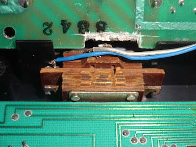
Some time in the 1980s, the owner thought it was a good idea to fit a power switch, although they regret that now.

And what a power switch, this thing is huge, probably rated 250V 10A, and it no longer appears to be working.

So big that the keyboard connection has had to be rewired. (I remember doing something similar with the keyboard ribbon on an Acorn Electron back in the 80s).

I have been asked me to take it back to stock, which makes sense, but that is going to leave a large hole in the case (around 12mm). I will have to deal with that later.

First I need to take the power switch out of circuit.

It looks like two of the traces have been cut. One break has been bridged back in place, and the switch is wired across the other break.

I cleaned all of that up and bridged both broken tracks. I also took the opportunity to replace the DC jack as the original was showing signs on corrosion on the contacts.

The Oric powers up, but is not working in one of the ways Oric's don't work. It shows this black and white pattern, normally only seen briefly at power on, 

This generally means the ULA is working and generating a video display, but the CPU has not got as far as initialising the display and clearing the screen.

This sometimes happens in a working machine as the reset circuitry in the Oric is a bit too minimal. Usually a power cycle fixes it. One of my own Oric-1's was particularly prone to this, and I ended up adding a microcontroller to fix it. Ah the dim and distant past where you could just order a microcontroller when you wanted one and use it to do nothing more than generate a clean reset pulse.

http://blog.tynemouthsoftware.co.uk/2016/05/oric-1-repair-part-1-reset-circuitry.html

I have tried forcing a reset, but that made no difference (pin 40 is reset, pin 1 is ground, it's easy for force a reset with a bit of wire).

This means the 6502 has not got as far as running the "setup the screen" code, so it could be the 6502 itself, could be the ROM chip, could be the DRAM, or any of the circuitry which controls them, some of which is in the ULA.

To rule a few of these things out, I swapped out the socketed chips, first the ULA and then then ROM, and I also removed the socketed AY-3 sound chip, since that is not required to boot.

I tried the Oric Diagnostics ROM, but that didn't run either.

Power was there, reset was (just about) there, and the clocks were all these. The databus was wobbling about reasonably well, but something wasn't right about the address bus.

The upper address lines were all changing rapidly, but the lower ones were not changing much. That's a bit unusual, as normally the code would run along for a while, with only the lowest bits clocking through the addresses, and jumping around a bit, but generally in the same areas.

Here was almost the reverse of that, it was like the code was stuck barely moving, but the upper lines were going wild. To be sure, I checked a working Oric and the pattern was much more what I would have expected.

I decided to remove the 6502, and test it out.

I had a VIC20 on the bench next to it (left over from comparison tests in last week's VIC20 repair).

I removed the good 6502 (with the blue sticker on) and installed the suspect 6502 from the Oric into the VIC20 and powered it on. It no longer booted. Looks like the 6502 was indeed bad.

I borrowed the known working 6520 from the VIC20 and tried that in the Oric (those blue circles are a dead give away).

Well, would you look at that, it worked!

I didn't want to steal the 6502 from the VIC, so I replaced it with a New Old Stock one ( https://www.thefuturewas8bit.com/shop/commodore/commodore-spares/6502cpu.html)

I did some more testing, with the Diag ROM, and all looks good.

Onto the next problem. That was working well on my bench power supply, but not with either of the two power supplies it arrived with.

The first is the original Oric one, and that is outputting somewhere between 3V and 5V. Clearly not the 9V it was meant to output (which is often more like 10-12V).

It is a very simple design and they are normally very reliable. Unfortunately, it is held together with melted plastic pins, so I doubt I will be able to take it apart and get it back together again in a safe manner (it also lacks shrouded pins, so is not ideal by modern safety standards).

The owner must have been aware of this not working as they also included a second power supply, one of those universal adjustable ones. That was only rated for 300mA, less that half the current the Oric had been drawing on the test bench.

That supply would almost be an option if I fitted a 7905 switching regulator replacement to reduce the amount of power wasted. 9V at two thirds of an amp is about 6W power into the board. It only needs about 3W for the actual electronics,  so about half of that is turned into heat by the 7905 linear regulator, The switching regulators only waste 5-10% of the power as heat, so reduce the input power requirements. I have fitten one in the past to another Oric.

Lets not get into why this is a 7905 rather than a 7805 at this point, I've covered that before. Let's just say the Oric is weird.

For the moment, that's all back together and I have ordered a new 9V power supply. I am going to do a bit more testing, load some games etc. to make sure everything else is working OK.

Now, what to do about that hole?

I was thinking of the kind of "vandal proof" switches that I used on my reverse PC build ( http://blog.tynemouthsoftware.co.uk/2017/06/reverse-pc-build.html), as either a power switch or a reset button, but they did not fit.

They clash with the modulator (even with the chunk previously taken out of the PCB below to fit the switch).

I thought maybe a power LED instead, and I found a couple of nice LED units, one black and one silver.

They also didn't fit, so instead, I've gone for a 10mm LED and a separate bezel.

I fitted a 2.2K resistor inline so that it is not blindingly bright.

That fits better, just clears the board and the wire sits in the gap next to the modulator.

I have wired the LED across the 9V input, right on the DC jack (whilst also sort of tidies up the repaired tracks a bit).

The cable is routed to keep it away from the external connectors and screw pillars.

The new LED lights to show when power is applied.

But it's not too bright, just a useful reminder the Oric is switched on, and it sort of matches the orange keys.

It would have been nice to have a power button or reset switch, but I think the LED is does the job of filling the hole at least. I just use an inline power switch (https://www.thefuturewas8bit.com/shop/power-supplies/inline-power-switch.html).

Now it's testing time.

That seems to work

The Oric is not great at loading from tape. It should be a lot better as it has a dedicated LM358 Op Amp to process the tape signal. However, all but the very early boards seems to have some variation of modification to the cassette input to the 6522 to try to make it better.

Here there is a 1K resistor and 2.2nF capacitor, both connected between 5V and the CB1 pin on the 6522, which is the tape signal input. There is also a 1nF capacitor inserted into the CB2 line, which I have not seen before. That is part of the control signal for the AY-3 sound chip.

Loading is the usual case of fiddling with the volume control. About 3/4 usually works on my trusty Sony TCM-818. I started with Chess.

When it loaded, it asked if I wanted it to beep when the computer made it's move.

I can see why, it was taking 5-10 minutes to make a move. Then, not only did it beep, but it had digitised speech! Let down slightly because I couldn't make out what it was meant to be saying. It was probably "Your move, Professor Falken".

I didn't dare make a bad move, or with that large red LED, it might have said "I'm sorry, Dave. I'm afraid I can't do that".

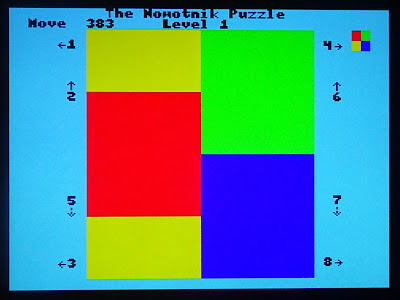
Next, Nowotnik Puzzle. A really interesting game I had not played before, sort of a 2 dimensional Rubik's cube.

The idea is to get it back to the picture in the top right, but you can only two rows of blocks at a time, either horizontally or vertically, by pressing the numbered keys.

It took me a while to work out the way to move things around. Getting one square of four is a bit like getting a side done on a Rubik's cube, you then need to try not to mess it up again.

Two squares, I am getting there.

Oooh, this is looking promising.

And it's completed. I enjoyed that, I will certainly be playing that again.

For some reason, I decided to listen to some Queen whilst playing this.


Advertisements

The NOS 6502 chips and inline power switches are available from The Future Was 8 bit.

The RGB to SCART cable and the cassette cables are from Retro Computer Shack.

Patreon

You can support me via Patreon, and get access to advance previews of posts like this and behind the scenes updates. These are often in more detail than I can fit in here. This now includes access to my Patreon only Discord server for even more regular updates.

https://www.patreon.com/tynemouthsoftware