This is an old post, preserved for reference.
The products and services mentioned within are no longer available.
This is the first part of an Oric-1 repair. I'll describe it's initial condition again, and cut down that section in the previous article. The repair starts after that.
This Oric-1 was 'untested' in ebay terminology - i.e. broken. I never plug anything in before checking it out. This is a case in point as to why that is a good policy.
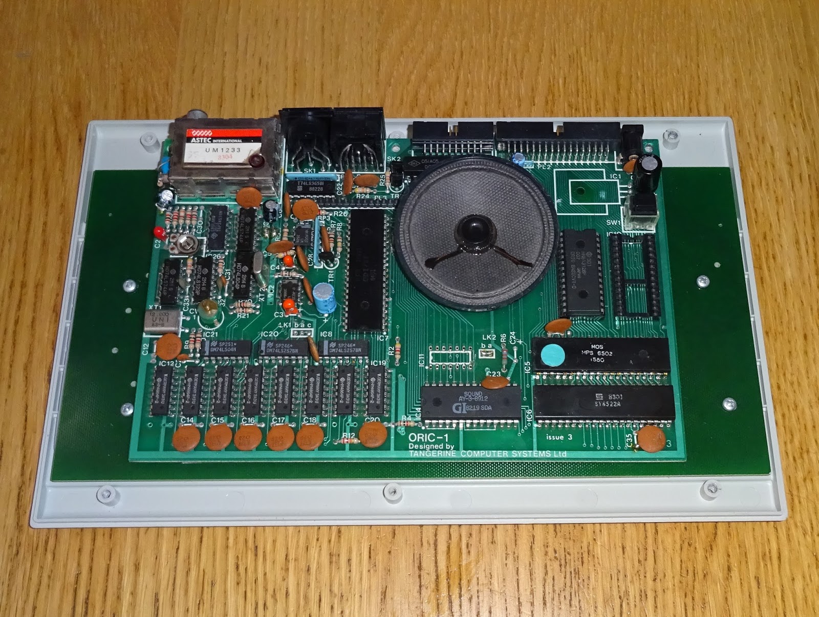
Inside there is a 3 terminal regulator missing. Not the usual 7805 I was expecting, but for some reason the Oric-1 uses a 7905 regulator. The 7905 is designed to take -9V DC and generate -5V. Here it's wired slightly oddly to take +9V and generate +5V. Why they didn't use the normal version I don't know.
This arrangement means that in normal operation the 0V rail inside the Oric is about 4V above the 0V rail of the power supply. If you happened to have a power supply where 0V was tied to mains earth (which is not unreasonable), and you plugged it into a TV or monitor with it's ground referenced to mains earth (which is quite possible), it would short out the 4V differential and the board would be running at 9V?
Anyway, it turns out a previous owner had bypassed the 7905 making it a 5V DC input That would make more sense, as long as it is clearly labelled, which it wasn't. There are also a few other suspicious mods, various extra capacitors scattered around the board, and some strange resistor and capacitor mod to the power feed to the modulator.
The Oric-1 originally had two 8K ROM chips. Later models had a single 16k chip. The board was designed for either arrangement, it was fitted with either two 8K ROMs and IC11, a 74LS00, or a single ROM and LK2 jumper link. This looks to have started as the two ROM version and been modified to a single ROM. The ROM fitted is an Oric-1 BASIC 1.0 mask ROM, so another machine has been involved. That may now be running with the two original ROM chips from this board.
The CPU is also not original and I'd hazard a guess it came from a mark 1 VIC20, as it is a 1980's date code MOS part, and I've seen blue stickers like that on many VICs. Looking again at these pictures, the date codes are all over the place, from 1980 to 1984. Many of the chips look to have been replaced at some point.
Feeding the board with 5V directly, it is not working, there is a nice pattern on the TV though. In these sort of situations, I tend not to trust previous repair work, when there is flux residue on lots of chips on the back of the board, you know someone has been messing around in there.
When chips have been removed and resoldered without sockets, it is sometimes difficult to know if any tracks or through hole vias have been damaged. These is some damage around where the 74LS00 was removed and not replaced, so I decided the best option was to remove the other chips which had been replaced in the past and check out the board.
Once the board was cleaned up, it was actually in reasonable condition, so I fitted sockets for the larger chips. I tested and replaced the TTL chips that had been removed, all were fine. I also removed the two ROM sockets and fitted a single socket since I would never be using a pair of 8K ROMs.
There were only meant to be a few electrolytic capacitors on the board, so I replaced those. I may install a 7905 (with additional heatsinking) or a switch mode replacement, but at this point I just tidied up the 7905 bypass. A large label will be attached to the case if I leave it like that.
I installed a set of known working set of chips (thanks to @futurewas8bit for the ROM images).
Retesting again it was still just showing the black and white boxes.
Back to first principles, power, reset, clock. The power is OK, 5V getting to all the chips, a bit of ripple, but not much. I tried adding some additional capacitance, but it didn't change that much and still showed the black and white bars. Slightly better now, with a temporary composite video modification.
The clock was also fine, 1MHz into and out of the 6502. The reset pulse didn't seem to be there, it was going high too fast and the CPU was not resetting. I shorted out the reset pin and it booted up!
I tried many times, but could not get it to start up itself without forcing a reset. The reset circuitry on the Oric-1 is as basic as you can get, a capacitor is charged up by a resistor and the voltage across it should initially be low enough to start the reset cycle, and after a second or so be high enough to complete it and start the chip running.
This wasn't working. I had already replaced the 1uF capacitor, but that and the original had tested fine. I did manage to get it partially working with a 10uF capacitor, sometimes it would start after about 5 seconds, other times it wouldn't. I tried several versions of the 6502 and with both the 6522 and AY-3-8912 removed as they both have reset connections, but it wouldn't start up without a kick.
Most of the other 6502 based systems I can think of use a 555 timer based reset circuit. The same RC circuit is used to trigger the 555 and generate a clean reset pulse of a defined period. As far as I can see all the Commodore 65xx based systems from the very first KIM-1 through to the Commodore 128 all used a 555, or half of a 556 to generate a clean reset pulse.
The BBC micro also uses a similar circuit. It is only the original Atari 2600 I can think of that used the RC circuit. In the later 2600 Jr and 400/800 series at least they use a logic gate to buffer the R/C signal.
Apparently the original design for the Commodore 264 series (plus/4, C16 etc.) used an RC, but the 555 circuit was reinstated when Bil Herd took over that project. Given the 555 one shot timer circuit had survived through so many machines and cost reduction exercises in Commodore, a company not known for extravagant additional circuitry, it must be necessary?
But the Oric-1 only has an RC on the reset pin. It seemed the thing to do was to fit a 555 based one-shot time circuit to generate a reset pulse. The output of the 555 is high during the pulse, then low, so the plan was to use a transistor on the output to pull the reset line low, connected where the capacitor was, leaving the resistor in place to pull it high in normal operation.
I tried to think of a way of adding that neatly. but one 8 pin chip, three resistors, three capacitor and a transistor are a little difficult to hide. I then decided to cheat.
It's still an 8 pin chip, an ATtiny25 microcontroller, but doesn't need all the other items, I've added a decoupling capacitor, force of habit. That will be setup to enable pin PB1 as an output, and drive it low. Wait 100mS then set it as an input. The existing 2K2 pullup resistor will then pull reset line high, the CPU will start up and the microcontroller will go to sleep. I've set it as an input rather than driving it high so that reset can still be pulled low by an external add on or reset switch.
I think it took longer to write that description than it did to write the code itself. With the chip programmed and the fuses set for brown out detection and the low power internal 128KHz RC oscillator divided by 8, it shouldn't draw much power or create any noise. To fit it to the board, I looked to the pads left when IC11 was removed.
IC11 was a 74LS00 quad two input NAND gate used to derive the chip select for the ROM chips when two 8K ROMs were used. It has 5V and ground, and several connections that just connect to other gates in the same chip. Only three pins on the microcontroller are need. The two power pins, pin 4 is ground, pin 8 is VCC, are fixed, but of the remaining six, any could be used as the output, and the rest set as high impedance inputs.
Ground is in the right place with the chip aligned to the right and the other two pins are connected to pads that were wired only to other pins on IC11. No tracks to cut, just 5V to apply to pin 8 and I can use pin 6 as reset, which I wired directly to pin 40 on the 6502. I added the decoupling capacitor on the back, directly across the chip.
I did try to use a ATtiny44, a 14 pin chip that would have fitted the original footprint, but the pins were in the wrong placed and I didn't want to cut any tracks. I don't think you would spot it unless you were looking for it, fits in quite nicely. The original capacitor on the reset circuit (C21) is removed.
With that fitted, it is now starting up every time. I initially used a 1 second delay, and dropped it down to the 100mS shown above, and it still seems fine. That is about what the BBC used, the Commodore PET had 1 second, and the C64 500mS.
Next step is to try to reinstate the original chips, fix the power supply and improve the video output with a permanent composite video modification or RGB to SCART.