Friday 29 July 2016

6502 Diagnostics Tester

This is an old post, preserved for reference.
The products and services mentioned within are no longer available.

I've been building a few more of the 6502 Diagnostics boards to run the PET diagnostics firmware.
It's a fairly simple build, but the microcontroller package is quite small and can be difficult to solder.
Before putting one of these anywhere near a PET, I want to make sure that all the pins are connected, and there are no shorts etc.
Most of the times I use a microcontroller, I would use the internal RC oscillator, or more often a crystal or ceramic resonator. In this case, the microcontroller is driven from the system clock, so it needs an external 1MHz clock fed to one of the pins. Once the configuration fuses are set to use an external clock, it is no longer possible to program it without that external clock being present. In order to program and test the boards, I need a clock and some way to monitor the pins. When testing the first ones, I used a signal generator and logic analyser, but that's not really practical to setup each time I built a batch.
I can't use the built in clock generator, so it needs an external clock. I looked at a few options, using a similar style to the PET, using a crystal and a couple of logic gates to form an oscillator, but I would need to add some more to divide that down to 1MHz. I also considered just using a 555 times, but that wouldn't be fast enough, I think a few hundred KHz is the limit there.
I then had a look around at self contained 4 pin crystal oscillator modules, I had a few, but they were all too high frequency. After looking at various options that were too fast, or too slow, and all involved a few too many parts, I went for an easier option.
This is an ATtiny45, a small cheap (<£1) 8 pin microcontroller. This has an internal RC oscillator and can be set to feed this to one of the output pins. The RC oscillator is 8MHz, but it can be set to divide by 8 internally, giving 1MHz. Perfect. In the end, I didn't actually write any code for this microcontroller. It was all done with the fuses. Set it to RC oscillator, divide by 8, clock out on PB4. For those playing along at home, this was all it took:
avrdude -v -pattiny45 -cusbtiny -e
        -U lfuse:w:0x22:m -U hfuse:w:0xdf:m -U efuse:w:0xff:m
With the clock sorted, I needed to add some way to test the output, lets face it, it was always going to be flashing LEDs. I had some 20 way LED bar modules I use for the IEEE-488 diagnostics board, so I used a couple of those. Nice and simple one LED per pin, LED on if the pin is high.
That fitted neatly on a small prototyping board, but there wasn't space for the usual SIL resistor arrays, I also didn't have enough of those at hand, so I went for adding those resistors on the back, using 1206 surface mount resistors soldered to a common ground wire.
That all worked out very neatly. The microcontroller is hidden under the socket, only three pins are connected, 0V, 5V and PB4 which is clock out that goes straight to the clock in pin of the IC socket.
There are two 0V and one 5V connection on the 6502 socket, these are wired so they will always be lit. The clock output will always show as half brightness as it is a 50% duty cycle square wave. It's a buffered output from the microcontroller, so is more than capable of driving an LED. Time for some testing.
I added various test patterns to the software to check for missing connections, shorted pins etc. Here it spotted two shorted pins on another board, you can just see the two faint LEDs on together. in the middle of the bottom row.
With all that verified and the normal firmware loaded, time to test the newly built 6502 diagnostics model on a real PET.
Working nicely (once I set the DIP switches correctly).
A useful bit of test kit for when I build these boards, and it should be useful for the future USB serial driven versions as well.

If you would like one of the 6502 diagnostics boards (not the LED tester board!) with PET diagnostics software, you can order one below.

Sunday 24 July 2016

VIC20 Penultimate Cartridge Preorder

This is an old post, preserved for reference.
The products and services mentioned within are no longer available.

I'm pleased to announce the VIC20 Penultimate Cartridge I have been working on is now going into production by www.thefuturewas8bit.com. Like the nicely cased SD2IEC they produce, the VIC20 Penultimate Cartridge is also going to have a custom case.
Taking styling cues from both the VIC20 and later Commodore 64 cartridge designs, it's going to look fantastic. The label is only on the top half of the case, so you can read it when it is inserted, unlike the original VIC20 cartridges, where you have to remove them to read the title. And let's face it, when this is installed, you're never going to want to remove it.
The colour should be close to that of the brown VIC20 utility cartridges, the thinking being that although VIC20 cases vary from bleached retrobrite white through to smokers teeth yellow, the keyboards are all still brown.
This case has been designed to accept standard VIC20 boards, including my current Penultimate Cartridge boards.
There are two buttons on the new case, so a new space invader shaped board has been designed. Rather than the section sticking out of the top, there are wings on the side with buttons for 'menu' and 'reset' in the corners.
The firmware is now at revision 5.0a, and includes 43 ROM titles, selectable via keyboard or joystick.
Included on there are text adventure cartridges which used to need the user to type 'SYS 32592' to start them. This has been automated, so they will run automatically.
From this menu you can also set common RAM sizes to exit to BASIC, or load a file browser from disk, ideally suited to loading FB20-8K from an SD2IEC. Block 5 RAM is cleared whenever it is used, to avoid auto starting anything you had previously loaded into there.
There is also an advanced menu where you can select which blocks of RAM to populate to suit any programs with particular requirements from 0K through to 35K.
The VIC20 Penultimate Cartridge is available to pre-order now from www.thefuturewas8bit.com. Or if you prefer, buy an uncased version now (while stocks last).

UPDATE: I've updated the firmware to V5.0c, and added a user guide and a few more ROMs

UPDATE: Great video review from GadgetUK164

2022 Update: The production version of the Penultimate Cartridge is now available from  The Future Was 8 bit

Thursday 7 July 2016

VIC20 Internal SD2IEC


If you've got a VIC20 or a Commodore 64 and you want a simple disk drive replacement, the solution is fairly straight forward, you get an SD2IEC.
These are some very nicely packaged versions from The Future Was 8 bit, in a variety of shades to suit a range of Commodore machines.
These work well with the new VIC20 Penultimate Cartridge, which can automatically start the file browser from its menu.
During the development I have been borrowing a clear SD2IEC from my clear cased C64C.
And also a nice VIC20 coloured one on my main VIC20, made out of recycled VIC20 cases.
The VIC20 I was using for development wasn't one of my best. It arrived with one of those Commodore power supplies where the 5V was more like 7.5V, and many of the chips on the board had been fried. I had to replace most of the chips to get it running, but it's been a useful test machine since most of those chips were now socketed.
Something I've been meaning to do for a while was try out the idea of an internal SD2IEC, so I thought this would be a good candidate.
The internal SD2IEC boards (the SD2IEC Classic V1.0) are similar to those used inside the normal SD2IEC units, but without the buttons. There are additional contacts at the edge of the board to fit buttons and duplicates of the onboard LEDs.
The only pins needed for the IEC bus are 6 at one end, so I fitted a 6 pin 0.1" header, soldered to each side of the board. You could just solder the wires directly, but I thought this would be neater and would allow it to be removed easily if necessary.
There are various points at which the wires can be attached, I chose a set of vias just before the 6pin DIN socket. These were a bit tarnished, but with some desolder braid and extra flux they cleaned up nicely.
I've marked the connection points, these are relevant to this revision of the board, the VIC20-CR 250403 / 251040-01 Rev D. Always a good idea to check continuity to the socket to make sure you have the right pins.
I've tapped 5V and ground at nearby vias and attached five wires to these five vias.
On the end I've fitted a 6 pin connector suitable to fit the 6 pin header (Harwin M20), and plugged this into the SD2IEC board.
I was initially thinking of resting this between the DIN sockets and the VIC shielding, but in the end I've gone for attaching it to the lid of the VIC shield with foam pads. Making sure the contacts are clear of the metalwork.
Testing this, the lights flash reassuringly and the file browser appears. If I were planning to close the case up, I think I would look at changing the VIC20's power LED for a tricolour one, red for power on and then amber for disk access.
This one, however, runs mainly without a lid, with the prototype Penultimate Cartridge installed, so the onboard LEDs are fine. My bench is now a little tidier.

Update: an internal SD2IEC for a C64C.

Saturday 2 July 2016

PET Diagnostics

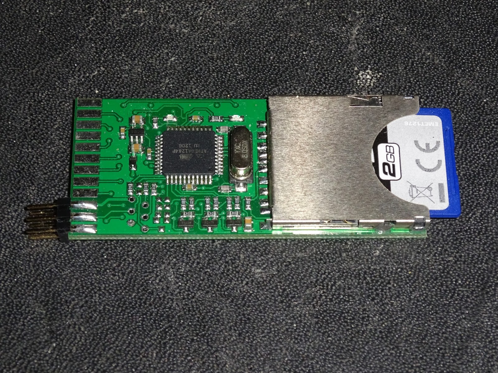
System like the VIC20 or Commodore 64 have cartridge slots, so can run diagnostic software from there. The PET does not, so this is my new 6502 diagnostics board, a board which fits in place of the 6502 CPU in systems such as the Commodore PET to run diagnostics checks on a non-functional PET.
It controls the system under test from the CPU socket in order to test RAM and ROM and other system functionality. This version has no external outputs (the 6 pin header is for programming), and instead uses the hosts video circuitry to report the results on screen.
The first application of this is on the Commodote PET, a fairly standard 6502 system with fixed areas of ROM and RAM (no paging is used until the 8296). This is running my PET diagnostics software which makes use of the PET screen and writes to its video RAM to generate a display.
Early Commodore PETs (the 2001, 2001N, 30xx and 9" versions of the 40xx) had no dedicated screen controller chip, and the video output was just whatever was written to the 1K of screen RAM. This leads to a common fault on these PETs of a screen full or random characters, which in many others systems would be a black screen error. These PETs will show this with no system RAM, system ROM and even with no CPU installed.
When the system is powered up with the 6502 diagnostics board in the CPU socket, it writes to the screen RAM and as long as that is working, a display is generated. Even if it is not working correctly, having known text written to the screen can often help diagnose what is wrong with the video circuits, in order to let you then get on with fixing the ROM or RAM or whatever else is wrong.
There are three tests implemented on the main screen. The first is testing main RAM. The PETs have between 8K and 32K of RAM. This is tested in 8 blocks of 1K, 2K or 4K, depending on the amount of RAM selected. The results from each block show which bits were bad within that block, and how many errors in total were detected. On early systems with 6550 or 2114 static RAM, each chip handles a 4 bit wide 1K block, so one bad RAM chip would show up as bits 7654 or 3210 faulty (or parts within).
Later systems used 4116 DRAMs, each a 1 bit wide 16K block. One of these being faulty will show up as errors on that bit over all the sections it covers. I may look at tying these up to IC numbers in a future version of the software. The counts shown are all hexadecimal, so 1000 errors is actually 0x1000 errors, or 4096 errors, or basically the whole 4K block.
The next test actually happened first, before drawing the screen, the video RAM was tested (since testing the video RAM writes the test characters all over the screen). The results are shown as one or two 1K block, for 40 or 80 column PETs. Errors again shown by bit. Here some partly faulty video RAM can also been seen in the occasional invalid character being displayed.
The third test on this page is ROM 7 blocks or 2K or 4K depending on the system. The test is based on a 16 bit CRC of the ROM. I test this multiple times and if the result is consistent, I use a lookup table to show which chip this is. If the CRC is not consistent, this points to a fault chip. There are weak pullups on the databus, so empty sockets give all 0xFF bytes and a consistent CRC.
The 8032 I was testing here had a faulty kernal ROM, which showed gave an inconsistent CRC. So I was able to go straight to that chip, desolder it and replace it with an EPROM and the machine was back in running order.
When there are multiple ROM or RAM errors, it could be data or address buffers or address decoding, or it could just be multiple failures. 4116 DRAM chips don't last well if one of the three supply rails they need fail. If you have multiple failures, it it sometimes a cheaper option to go for a ROM/RAM replacement board, rather than replacing lots of chips. It can also be used to add more RAM or upgrade the version of BASIC.
The socket numbers are displayed next to the ROM results. I have actually had several PET boards in for repair which had all the right chips, but in the wrong socket. All being well, all those test pass and it holds on that screen for 10 seconds to check the results.
It then clears the screen and shows a character map. After a few seconds, the character set is changed and the alternate graphics / business characters can be seen. The PET has two character sets controlled by an IO pin setting an address line on the character ROM, so only one can be displayed at a time.
The original PET 2001 always had upper case characters in the range 00-1F region, and alternated graphics or lower case in the 40-5F range. Later PETs decided to confuse things and have upper case at 00-1F and graphics at 40-5F in graphics mode, but to switch things around and have lower case 00-1F and upper case 40-5F, which is why you occasionally get some software with annoying rEVERSE cAPITALISATION or symbols where the upper case characters should be like \aze or |litz.
After the two character maps, it goes back around and repeats all the tests, so you can just leave this running and check back to see if there are any changes to the ROM and RAM tests once the system warms up.
There are different amounts of ROM and RAM in PET systems, as well as other changes, such as the reversed character sets on the original 2001, and the CRTC initialisation on 12" 4032 and 8032 machines. Rater than having different builds for each machine, I have used a set of DIP switches to select the machine.
Sw1
Sw2
Sw3
Machine
ROM
RAM
Video
0
0
0
12" 4032
6x4K + 2K
32K
CRTC 40 col 50Hz
0
0
1
12" 4032
6x4K + 2K
32K
CRTC 40 col 60Hz
0
1
0
8032
6x4K + 2K
32K
CRTC 80 col 50Hz
0
1
1
8032
6x4K + 2K
32K
CRTC 80 col 60Hz
1
0
0
2001 *
7 x 2K
8K
no CRTC 40 col
1
0
1
2001N-8/3008/4008
6x4K + 2K
8K
no CRTC 40 col
1
1
0
2001N-16/3016/4016
6x4K + 2K
16K
no CRTC 40 col
1
1
1
2001N-32/3032/4032
6x4K + 2K
32K
no CRTC 40 col

If the machines is one of the 12" 4032 or 8032 systems with a CRTC chip controlling the video, this needs to be correctly initialised before the screen will show anything, so 12" 4032 is the default setting.
Most of these are 40 column systems, the 80 column version just uses the left hand side of the screen, other than the border and title.
Using the PET diagnostics is just a case of removing the 6502 CPU, installing the 6502 diagnostics board in it's place and switching on. There is no 6502 processor in this system. The only code running is on the microcontroller on the 6502 diagnostics board.
I have various plans for this, I will be adding a second screen of tests for the VIA and PIA chips and the IEEE-488 port and any other things I can think of testing. I am also looking at adding a serial output to give the results on systems with faulty displays, but the real answer is fix the display first, then you can get on with testing the rest.

If you would like one of these 6502 diagnostics boards with PET diagnostics software, PET diagnostics board is now available from my Tindie store.

PET Diagnostics
Update:
The new versions of this board are now red.
There is now a notch at the pin 1 end to ensure you get it the right way around.

Note:
* There appears to be some timing issues on 2001 boards with 6540 ROMs or 6550 RAM, so consider those not supported until I resolving the timing issues.

2024 Update:

The PET Diagnostics modules are available from my SellMyRetro store: