This is an old post, preserved for reference.
The products and services mentioned within are no longer available.
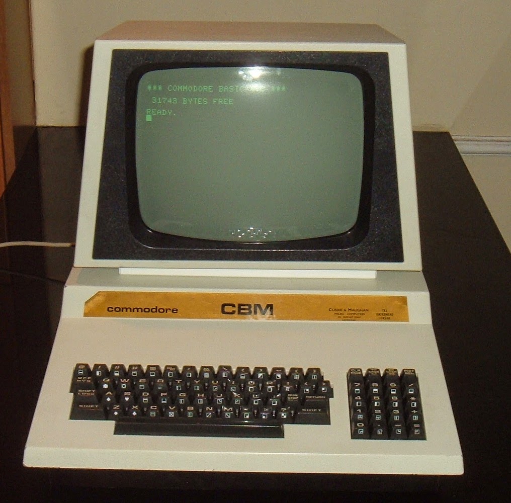
The
Commodore Pet 4032 is now complete, and ready to use, I just need to get some software on there.
I have some Pet software on 8250 style floppy disks, but have yet to repair the 8250 drive. For other Commodore computers, I use the SD2IEC which plugs into the IEC port and provides easy access to .PRG and .D64 files.
The Pet doesn't have an IEC port, so unfortunately, I can't use that. It does have IEE488, which is parallel, and is what the IEC serial interface was based on. I have a few ideas for an SD card based solution, but for the moment, I'm relying on the cassette ports, and the
recently refurbished Datasettes. Looking around, I found
this page, where the author had used a Commodore 64 to assist in the transfer process.
The idea was to load the program into the Commodore 64, and then save it to tape. The tape could then be loaded on the Pet. Not quite as straight forward, as the load addresses are different, so there is a series of steps to follow on the Pet.
- NEW - clears existing programs
- 0 REM - start a new program with line 0
- LOAD - load the program
- SYS 1024 - start the system monitor program
- M 0401 0408 - display memory from address 0x0401 to 0x0408
- cursor up and change the line to start :0401 01 08 - this points to 0x0801, the address where the code from the C64 was loaded
- X - exit the monitor
- 0 - remove line 0 and relocate the rest of the code
- SAVE "name" - save the program to tape
It looks a bit of a faff, but once you've done it a few times, it's quite quick.
To get programs on the C64, I added a directory to the SD2IEC SD card and copied on a selection of Pet .prg files. After a few successful transfers, I wondered if I could cut out the step of saving to tape on the C64, rewinding it and then loading it into the Pet. The cassette port is quite simple, It is a 12 pin connector, but the top and bottom rows are the same, so it's only 6. Would have been nice if they had reversed the bottom row, so the connector could go either way up, but never mind. The connections are as follows;
- GND
- 5V - permanent 5V supply
- Motor - switched unregulated 9V
- Read - data in
- Write - data out
- Switch - connect to GND when play (or any of the other keys) is pressed
So there is a data in and a data out, both TTL level, both pretty much direct to PIA I/O pins. All the analogue stuff is handled in the datasette. So can I just connect them together? It turns out no. Whether by design or mistake, the signals are inverted. I inverted the signal using a 74LS04 inverter and fed the inverted signal into the Pet.
Bingo, it worked. I wanted to make a lead up, and didn't think I would fit a 14 pin chip into the plug, so I tried a simple NPN transistor inverter, and that also worked fine,
It actually gave a slightly cleaner signal than the TTL gate did as it was pretty much full swing on the supply rails (top is output, bottom is input, both 2V per division).
I built this up into a cable, with the components wired directly to the plug. I used a 2N3904 but any NPN transistor should do. The emitter is wired to 0V. The base is wired via a 1K resistor to the write output of the C64. The collector is connected to the read input of the Pet, and pulled high via a 10K resistor to 5V.
The switch input on both plugs is wired to 0V.
And that's it. I found 15 way D connector hoods were a close fit. The screw holes didn't match, so these are just held on with cable ties.
With the cable in place, it simplified the process as I could load the program on the C64. Setup the Pet with 0 REM and then LOAD and as soon as I start the SAVE on the C64, it loads on the Pet. Then just sort out the load address as above and save to cassette.
Another nice thing about the Pet is that is has two cassette ports, the rear is port 1, the side is port 2. So I can do LOAD (which is short for LOAD "",1), and then when finished, SAVE "name",2. So no unplugging is required for the whole transfer process.
Finally some new software, here I'm trying some of the newly written Pet games from
Revival Studios.
These are now free downloads. I particularly like Down, a very simple but fast and addictive game. Too fast in fact to be able to take any decent photos. Sorry.
Update: This doesn't seem to work with some machine code only programs, and ones that load at unusual addresses. Bit it's fine things like space invaders, fire, blitz etc. Also watch out for ones that include the '
killer poke' code 'POKE 59458,62'. That normally appears at the start of the code, so just remove the offending code before saving. On early Pets, it can speed up the video. This isn't required on the later CRTC based pets, where it causes monitor to lose vertical sync, generating a bright spot or line which could damage the monitor after a while.