I am in the process of writing a post about how the video system on the Jupiter Ace works, and that is coming together nicely, but it would be useful if I had a Jupiter Ace I could wire up to a logic analyser to get some traces.
I do have lots of Minstrel 4th's and Minstrel 4D's, but those have all of the counter logic inside the microcontroller, so I really need something that uses the original schematic that I can poke things at.
Unfortunately, I don't have a real Jupiter Ace, but I remember about 5 years ago (January 2019 I think), I did have a go at building a clone of the Jupiter Ace, with pretty much the original schematic. This would be ideal, if I could just get it to work.......
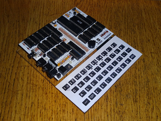
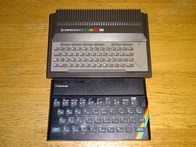
At the time I had the Minstrel 2 and 3 boards that used the ZX81 form factor, so it seemed a good idea to use the same for this.

It was quite a squeeze to fit it in there, with all the logic chips and half of the worlds supply of 1K resistors.

The original Ace had three pairs of 2114 static RAM chips giving the three 1K blocks, system RAM, video RAM and font RAM. I can't get new 2114 chips, and the used / New Old Stock ones are not always very good, so I decided to replace all of them with three skinny DIP 32K SRAM chips.

(yes, I wired one of the pins wrong on the 74LS166)
You might think that is a bit wasteful, but they are cheaper than 2114s, and they are even cheaper than the 8K versions of the same thing. The two video parts only use 1K, the main RAM provides the 1K system RAM and also a 16K expansion.

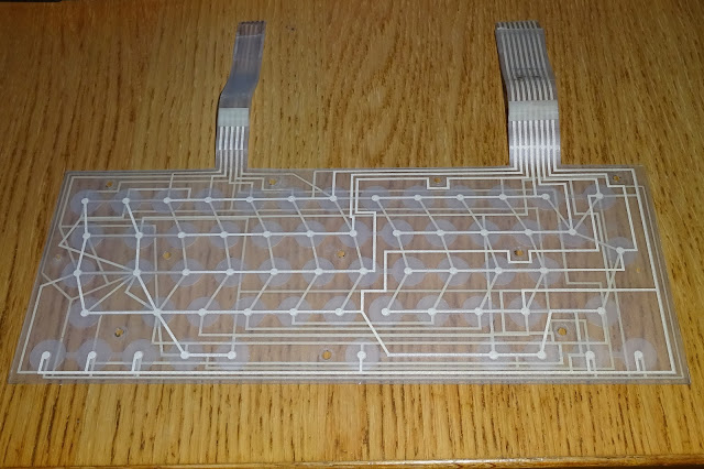
I put it all together with a ZX81 replacement keyboard membrane, with an overlay in the style of the Ace keyboard.

When I came to fire it up, it seemed to work, but there were some random characters on the screen, and some of the characters were corrupted.

The video was also very fuzzy, I had based the composite video mixer and amplifier on the Jupiter Ace 4000 version which had composite video out (the original Ace didn't), so I thought I would use that. But it was a bit ropey, so I later adapted it to the same circuit I had used on the Minstrels.

The video signal was much clearer, but the character corruption was still there, and seemed to get worse the more you used it. I couldn't work out what was wrong, but it did seem to be otherwise working.
At the same time, I had designed another board, one which used dual port RAM to simplify things, and that one also just about worked, but seemed a better place to start from for what became the Minstrel 4th and later the Minstrel 4D - read about that here - http://blog.tynemouthsoftware.co.uk/2020/05/minstrel-goes-forth.html

I did return to the original board a few times. At seems at this point I had decided to call it JACK (Jupiter Ace Computer Kit). It seems I decided Minstrel 4th was a better name.

I am not even sure what all this was trying to address, but it didn't seem to fix any problems.

Another few months later, I tried again. I noticed the clock signal was a bit weak, so I tried replacing the transistor based crystal oscillator with one made from two inverters, a more tried and tested solution. Yes, that is a bit of a cut up one of my RC2014 modules. (I later found out that the weak clock was actually down to a bad gate on the 74LS86 that buffered the clock, when I tried to use that spare gate to invert the video)

That seemed to help, and with some of the other modifications, it had reached the point where it would start with a clear screen one reset out of three, but even when it was clear, you could run VLIST and all would look fine until it got to the bottom line and then bits of the screen would get corrupted.

By this point, the Minstrel 4th was going well, so I put this away in a box again and forgot about it.
Roll forward to today, and it would be quite useful if I could get this to it to work, so back out of the box and onto the bench.
I removed most of the previous mods to go back to basically what was in the schematic, with the exception of the alternative oscillator and composite video buffer circuits.

I decided to analyse the problem further, now I have a better scope and a better logic analyser and what passes for a fresh pair of eyes.

My initial thought was that there were unintentional writes happening to the two video RAM chips, so I probed those and looked out for anything unusual.
Because of the way the video system works (see the future blog post), the video RAM and character RAM are both enabled most of the time as they are generating the video signal.

I did see occasional glitches in the chip enable signals. Very short and only a single sample wide when scanning at 50MHz. But the edge that creates could be enough to trigger a write cycle in the RAM chip, if they occurred when write was low.

Ah, there you are, that would trigger an unwanted video RAM write cycle, and would explain the corruption.
That probably wasn't an issue with the slower 2114 SRAM chips originally used, but because the modern 71256 chips I used here were a lot faster, they were treating those glitches as edges and getting corrupted.
Those signals are produced from an assortment of logic gates and a slightly strange loop around buffer based delay.
I decided I wouldn't change any of those, since this was just due to faster RAM, I tried to fix it just before the signal gets to the RAM chips. I tried gating the write signal with the 6.5MHz clock, that moved the write pulses away from the jagged edge where the occasional glitches were occurring. It does mean multiple write pulses, but I don't think that will be a problem. I could maybe use the 3.25MHz clock, but this seems to work nicely as is.

It did mean one more chip was required, but I used a 74LS00, and if I was to do another spin of the board, a single 74LS00 could do both the crystal oscillator, clock buffer and the clock gating of the video RAM write pulse, keeping all the 6.5MHz signals in one place. (would anyone be interested if I was to do another revision of this board to fix the various issues and make it available as a kit?)

Even with the output buffer changed to the circuit I used on the other Minstrels, the video output of this circuit is still not great. It has no back porch to set the black level, but the screen is all black, so it just needs good strong white peaks, but the 74LS series logic never really generates those, so the screen is a bit grey and washed out. I probably need to tweak the resistor values in the buffer circuit to get the levels better.

Ideally I would also add a back porch generation circuit to make it more correct, and maybe switch over the 74HC or 74HCT logic, but this is good enough for the moment.
And there you go, perfect vlist with no corruption.

The 16K expansion is working with the top of RAM showing as 32K, and all the character set seems to be printing correctly with no corruption.

I did not have much luck loading programs from cassette, as seems typical with the Jupiter Ace, so in the end I just wired up the ear input to the mic output of a Minstrel 4D.

I loaded the built-in Tut Tut on the 4D and then typed save TUTTUT on there and load TUTTUT on the Jupiter Ace clone and it loaded first time.

This is a good test as it modifies the character set.

That all looks good.

I always like to play out at least the first level.

All good apart from the sound not working, the speaker is just clicking. I will need to have a look at that, I think it was working, so was maybe damaged when I cleaned the board with IPA. The video side of things is all working which was my main aim, and all I need for now.

Why didn't I wire the ear input to the signal out of the microcontroller on the 4D, then you could have loaded things more easily? Ah well (as I found out after trying that a few too many times before I realised), it always loads in turbo mode, and of course the Ace clone doesn't have a turbo, so has to load at slow speed.
I am not used to running the Ace in it's normal colour scheme. I normally chose black text, white background on the Minstrel 4D. Makes it a sort of "3D Monster maze: Night vision edition".

That also highlights a mistake I made with the keyboard overlays. The up / down / left / right keys are on 5, 6, 7 and 8, the same as the ZX81 etc. But, for reasons best known to themselves, 6 and 7, down and up are reversed. I didn't have a working Jupiter Ace at the time I did those, so I didn't realise, and left the arrow graphics as they had been on the ZX80, which is wrong.

I still managed to find the exit in the end though.

Look out for the "How the Jupiter Ace Generates Video" post coming soon.
Advertisements
Minstrel 4D
The Minstrel 4D is a much more reliable and usable Jupiter Ace compatible computer, with all the extras like a joystick interface, SD card loader, RC2014 expansion bus etc. Available in kit and built form from The Future Was 8 bit.
https://tfw8b.com/product/minstrel-4d-turbo-jupiter-ace-compatible-computer-kit/
More info in a previous post:
http://blog.tynemouthsoftware.co.uk/2022/08/minstrel-4d-overview.html

Patreon
You can support me via Patreon, and get access to advance previews of posts like this and behind the scenes updates. These are often in more detail than I can fit in here, and Patreon is currently getting a lot development logs on a new project at the moment. This also includes access to my Patreon only Discord server for even more regular updates.
https://www.patreon.com/tynemouthsoftware