Thursday 31 July 2014

Dymo Label Maker PnP Review

This is an old post, preserved for reference.
The products and services mentioned within are no longer available.

I've been having a well overdue tidy up of the workshop. As part of that, I've bought couple of another cabinets of plastic storage drawers. After the mammoth task of sorting things into the drawers come the problem of labelling the drawers. In the past I've tried different things, writing on paper labels, printing on labels, printing and then cutting out little bits of paper. Time for something different.
I have an old Dymo labeller which is the traditional emboss letters onto thick plastic tape type thing. I use these for serial numbers on the USB keyboards, as they are seem to fit. I think they still sell these, now called '3D' label printers.
However, they aren't really ideal for this task as there are only upper case, no " (for inches), and a limited number of characters. So I looked at a new printer, and found this one, also from Dymo.
This is the Label Maker Plug'n'Play. The pack is actually sold as two packs of D1 tape with a free printer, and was less than £20 on Amazon. It's a USB label printer, which is advertised as plug and play, no software to install, no batteries etc. Well that's not entirely true, there is software to install, and there is an internal battery, but you shouldn't have to worry about them. The battery is Li-ion type which presumably charges up whilst it is plugged in and provides extra power for the mechanics of the printer.
The tapes supplied were 9mm yellow and 12mm white. I also needed 9mm white, so I bought one of those as well (£7.50 for 7m, not too bad).
The unit is small (150mm x 150mm x 50mm) and the only connector is a standard USB socket. There is a power button on the top with a blue LED, and a button to cut the label off (as that doesn't happen automatically). Slightly oddly, the labels come out upside down.
The software appears as a USB drive when you plug it into the PC, and can run from there, it would autorun if you have that enabled. I downloaded a later version from their website. It installs one of those annoying things which runs in the taskbar, taking a small but unnecessary amount of screen space and memory. Easy to disable though. It's also fairly easy to use, designed to appear like Microsoft Word (the proper versions, not 2013/365 style). The resizing of text areas seems a little counter intuitive, but I managed to generate all the labels I needed.
A nice feature is that the width can be fixed, so I found that 61mm was ideal for these drawers as it slid into the slot on the front of the drawers without actually needing to remove the backing and stick them on.
I got all of these drawers labelled out of the one roll, and there is still a fair bit left.
Now time to get some work done and inevitably mess everything up again.

2022 Update: I've now had three or four of these, the batteries within wear out and the replacements are more expensive that the printers. I've also had one were one of the pixels on the print element went bad, but luckily I have several spare units.

Tuesday 22 July 2014

ZX81 internal 16K RAM

This is an old post, preserved for reference.
The products and services mentioned within are no longer available.

Here we have a ZX81 with an unusual RAM chip. It is a MK4801AP-5, a 1K static RAM made by Mostek (not to be confused with MOS technology owned by Sinclair's arch rivals Commodore).
Sadly, it's not working, and it appears to be that RAM at fault. The screen is showing what looks like the loading screen on the quiet bits of the tape. It is easy to test this, by plugging in a RAM pack, as this disables the onboard RAM. That works fine, so time to remove the RAM.
In this state, it can be used fine with a RAM pack, and so is an option to leave it like this. However, the ZX81 board has positions for various configurations of RAM, 1K or 2K 24 pin (as fitted) or 28 pin.
There are also spaces for 2x 18pin 2114 SRAMs, as on this other board. I have a supply of spare 2114s, so I was about to fit sockets like this. Then I thought this would be a good opportunity to try out upgrading the onboard RAM. There are various options for this, the chips I have to hand are 32K, and it is possible to add 32K RAM, but this requires some additional logic, see this article for more info. The easier option is just to ignore half of the chip and get 16K RAM. That is fine because most of the software is designed for 16K.
The original chip was 24 pin, the new RAM is 28 pin. There are holes for a 28 pin socket, but there are a few differences between the way that socket is wired, and the pinout of a 62256 32K SRAM.
PinSocket62256Connection
1RefreshA14A11
2VCCA12VCC
26VCCA13A12
23WEA11A13
21VCC/A10A10A10
Pin 21 is set to either VCC or A10 by jumpers L1 and L2, so L2 needs to be fitted to use A10. That leaves 4 pins that need to be changed. Actually it's only three. The chips is 32K, so there is one additional address line that isn't being used and should be tied high or low. Ideally, that would be A14, but with RAM chips it doesn't actually matter what order the address lines are in ,or the data lines for that matter. There are a few options here, I've seen some people do this by bending out the legs of the chips and connecting from the bent leg to an appropriate via on the board. I prefer to leave the legs straight and make the changes on the back of the board.
Pin 2 is a problem as the VCC track goes through the pad for the pin on the top layer, so I've left that one as is, so that leaves three tracks to cut. Pin 26 is connected to VCC on the top AND bottom layer, so both need to be cut, refresh to pin 1 and WE to pin 23 can be cut on the bottom later.
A10 is connected to pin 21 via L2. The remaining pins can then be connected to the next three address lines, A11, A12 and A13. These can be found at the near end of the diodes next to the keyboard connector. D1, D3 and D5. Again the order doesn't matter, so I've gone for the nearest.
I've highlighted the changes above. Doing those changes under the board leaves the top neat and tidy.
The final look is almost as if it was designed to go there.
Once done, time to power up and wait for the K. So far so good. The usual test is to run
  • PRINT PEEK 16388+256*PEEK 16389
This gives 32768, showing the top of the RAM is at 32K. The first 16K is the ROM, so that means it has recognised 16K of RAM. Time for some proper testing, the copy of 3D Monster Maze I've been using to test ZX81's for over 30 years!
And away we go, Rex indeed lies in wait.
Well I did have to test it thoroughly. That all seems to work, and is now less susceptible to RAM pack wobble. The board with 2x 2114 chips draws around 400mA. With a single 4118 RAM chip, the current drawn was around 410mA. With a 16K RAM pack was 540mA. This newly modified board draws only 300mA, so less strain on the 7805 regulator which should now run a bit cooler.
I may have eluded Rex this time, but he is angry and I'll need more luck next time....

UPDATE: I can now offer a fitting service if you have a ZX81 that needs an internal RAM update, or composite video modification, voltage regulator switch mode replacement etc. Contact me if you are interested.

UPDATE 2: Some more photos, this is the memory size check:
The result is 32768 as expected (16K ROM and 16K RAM).

UPDATE 3: See also a version of this mod which does not require tracks to be cut.

Friday 18 July 2014

Commodore 64 PLA replacement - Mark II

This is an old post, preserved for reference.
The products and services mentioned within are no longer available.

I previously looked for a replacement for the Commodore 64 PLA, and tried an EPROM based solution. This sort of worked, but only on some systems, and was basically limited due to timing issues.
The PLA basically has 16 inputs (17 including CE) and 8 outputs. Replacing those is tricky as there aren't suitable chips of that size available. The solution I have come up with is to use two chips with 17 inputs and 4 outputs each, giving the required number of pins. They can sit either side of the rows of pins in what used to be called a butterfly adapter.

The chips I have used are GAL22V10s, these have 22 I/O pins, 10 of which can be outputs. That seems to add up, and leaves one spare pin. I have connected that between the two devices as it may be required for timing reasons.


The equations are available on the nets, and described in fantastic detail in the article The C64 PLA Dissected. I've split the connections according to the easiest wiring and in a combination of optimism and laziness, went straight to PCB. It's a small board, 1" x 1.5", so doesn't interfere with the surrounding components.

One of the reasons the EPROM based solutions have problems is timing, mainly around the CASRAM signal. This should be activated slightly later than the others, to avoid conflicts. It's basically a catch all, if none of the other devices, are activated, access the RAM. To achieve a slightly longer propagation delay, I've generated the signal on the left chip and passed it through to the right chip which passes it to the C64 board (when the chip enable is active anyway). This double delay seems to do the job nicely.
I have some spare boards, so contact me if you would like a PCB or a completed module.

2022 Update: The timing required seems to vary from board to board. These sort of worked, but not universally, same as the EPROM version.

6502 ROM / RAM Replacement

This is an old post, preserved for reference.
The products and services mentioned within are no longer available.

When fixing old computers, a frequent problem is 'black screen', where the computer appears to be powered on, but nothing appears on the screen. Many things can cause this, failure of the CPU, ROM, RAM or the glue logic in between, or the video out or other peripheral items. It's often a process of elimination, starting by removing unnecessary items, and swapping out the socketed chips one by one.
Various things can help with this, diagnostic cartridges like these run their own code either without needing RAM (or sometimes have their own RAM), and can identify various type of problems. But these are not always an option, in computers which don't have cartridge slots for a start. In trying to diagnose some issues with a Commodore Pet, I looked around at various solutions to this, such as bitfixer's Pet Vet, and Nicolas Welte's Universal 6502 RAM/ROM Expansion. Both essentially do the same thing, they plug into the 6502 CPU socket, and selectively isolate the CPU from the rest of the system. They can be configured so that any ROM access uses the copies of the system ROMs (or even different ROMs) on the expansion board, rather than the ones on the main board which may be faulty. It does the same from RAM access, it can use RAM on the expansion board to replace and/or expand the main board RAM.
The universal RAM / ROM expansion has some RAM and ROM and uses a gate array as glue logic, and dip switches to select options. The Pet Vet is a slightly more complicated solution, in that it has RAM over the entire address range, and a microcontroller. At power on, the microcontroller writes the contents of ROM images into the RAM and loads a truth table into a smaller RAM to work as address decoding glue logic. It also has a serial interface to control things.
I like the idea of the simpler unit, and tried a few times to contact the author of the universal ROM RAM board to buy a board or a kit, but didn't get any response. I'm not sure if the page is still active, since the news page was last updated in 2007. There are however, Eagle PCB files and JEDEC files for the GALs, so I thought I'd build my own. The page describes a later mod to add a jumper for 15xx disk drive memory maps, but the PCB files are an older version. I converted the Eagle files to Diptrace, added this jumper and made a few changes to the routing (force of habit, I like neat traces).
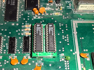
The layout is quite tight, with the CPU pass through inline with the CPU socket, and two TTL chips live under the larger sockets. Testing was as described on the site, the usual visual inspection, and then deep intake of breath turning it on for the first time.
The first test was with no ROM or RAM, and a jumper wire to replace the GAL and set the 245 to just pass through to the main board. Obviously, testing at this stage is best with an already working computer, in this case a VIC 20 CR.
So far so good, so time to install the GAL, a small programmable logic device with 16 inputs, 8 of which can be outputs (GAL16V8). This replaces a pile of TTL chips, and also allows the logic to be changed for different memory maps.With all the DIP switches off, this should also pass through.
Add ROM, and the system ROMs can be replaced, add RAM and the system can be selectively expanded.
Here is the VIC20 with the system ROM replaced and a full 32K of RAM (of which 28159 bytes are available).
It stands off the board via an extra DIP socket added to the bottom, but that isn't enough for the original version of the VIC 20 with the big heatsink and plethora of 2114 SRAMs. It needs another socket in the stack.
Here I've found yet another use for plastic business cards (I grabbed a pile when some people were leaving a company I was working for). They are useful for paint scraping, label removing, opening plastic tab cases, and now insulating 6502 ROM / RAM replacement boards in VIC 20s. This VIC 20 was showing a black screen. Rather than swapping out all the chips one by one, I was able to confirm it was the ROM chip by just removing the CPU and installing this board. A spare ROM chip later and it was up and running again.
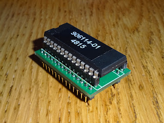
Option ROMs can also be included in the image, and separately enabled. The board has space for a 1Mbit EPROM, so that would be 4 system ROM images and 4 option ROMs. In this case, I've just used a 27C256 with a fixed image of the standard PAL ROM images, and a VIC20 diagnostic tool in the option ROM slot. The original page talks about software to load ROM images into EEPROM using the VIC20, but I haven't looked into that as the downloads appear to be missing.
One thing to note, some of the RAM inside the VIC20 is used by the VIC chip to build the display, so the RAM on this board does not replace that. I've tried on a board where I've had to replace all the SRAM, so it is socketed. It appears to work with at minimum the left hand 6116 for screen RAM and the right hand 2114 as Colour RAM. It does mean you could remove the other RAM (particularly if it's faulty), and the original ROMs and reduce the power consumption.
Now that's built and tested, I'll need to modify the GAL code to fit the PET 8032 memory map and I can get on with testing that. I'll also have a go at a BBC micro version, should be good for that. I may do another spin of the board with a power LED and a reset button, but I still have a number of these boards available, so if you want a board or a complete unit and can't get in touch with the original author, contact me.

UPDATE # 1
This has now been used successfully to assist with my Commodore Pet 4032 restoration.

UPDATE # 2:
The new V2.0 6502 ROM/RAM boards are available now.

UPDATE #3
The new V3.1 ROM/RAM boards are available now

UPDATE #4
New smaller PET ROM/RAM boards are available now, specifically to repair/upgrade Commodore PET machines.

UPDATE #5

These boards are available to buy from my Tindie Store and TheFutureWas8Bit.

2022 Update: This redesigned small version of the PET ROM/RAM boards are still available from  TFW8b.com 

Wednesday 16 July 2014

Raspberry Pi Model B+

This is an old post, preserved for reference.
The products and services mentioned within are no longer available.

Dear Raspberry Pi Foundation, thank you for making my life a little easier.
The new release of the Raspberry Pi, the Model B+, has a number of improvements over the previous Model B, which should make life easier for those integrating the Pi, as I do with my USB Keyboards.
So what's inside the box? Well, a slightly smaller Pi. The main connectors are now on just two sides, rather than all four sides as it used to be. The USB jacks are now inline with the edge of the board, and there are now two of them, giving 4 USB ports. Theese ports are also now inline with the RJ45 magjack for the LAN. The network activity indicators are now built in, and the power and disk activity now moved to the other edge.
You can see the evolution from the original release of the Pi on the left, through the first revision which had two mounting holes added, to the new board, with four mounting holes at the corners. There are also more pins on the GPIO, it's now 40 pin, so time to dig out all those IDE cables which were also 40 pin.
The audio has been improved, and the audio and composite video have been combined into a single 4 pole 3.5mm jack. Power consumption should also be improved by use of switch mode regulators rather than linear as in the previous models. On the back, the SD card has been replaced with a micro SD socket.
Again, this overhangs less than the previous SD card slot, and should be more reliable. All these changes of course mean it will no longer fit in most of the current cases. They say old model B will remain on sale, probably until all the case manufacturers have sold their remaining stock of old style cases. Look out for some offers soon.
Here it is with its the namesake, the BBC Model B+, the last revision of the BBC Micro in the original case (the next was the wider BBC Master). 30 years later, this new B+ is 512MB, only 4000 times more memory than the B+ 128K.
I'll be using one of these in the next casemod (the Pi, not the BBC), so it will be interesting to see how much better it fairs.
In previous builds, it has sometimes been necessary to remove some or all of the connectors in order to fit it in the case, hopefully I'll not have to do that next time.