Showing posts with label Library. Show all posts

Saturday, 28 September 2013

Arduino TV Out Terminal Library

This is an old post, preserved for reference.
The products and services mentioned within are no longer available.

This is an update to the library I have written for the Arduino which makes use of Grant Searle's Video Processor. Grant has recently updated his video processor code to support 40 character mode as well as the original 80 character mode, added a second font and a double line mode. There is now also a 160x100 pixel graphics mode.
The principal is this, you have an Arduino with your code in and this library, and connected to that you have a second ATMega328P (the same chip as is used in the Arduino) and a 74HCT166 shift register. Together they do all the work involved in generating a composite video signal suitable to connect to a TV or video monitor. You can build up these additional components on breadboard, or I have build a shield which fits onto the Arduino with all the required components on. The DIP switches select the default font and communication settings.
Interfacing between the Arduino and the video processor can be done in three ways. The original way was an 8 wire parallel bus with 2 handshaking control lines. A second mode was later added which allowed this to be reduced to 4 wires and 2 handshaking lines. The third method uses 2 wires in TWI or I2C mode, which was originally a fork of the code as part of an earlier version of this library, but has now been rolled into the main code. (Note: the diagram below shows shift/load connected to the ATmega in the way I had originally connected it. Since this post, Grant has changed the code to use PC3 (A3) for shift load).
The pin assignment on the video processor has been updated so that the two TWI pins will always be connected (they are used for handshaking in 4-bit and 8-bit modes). The library and shield support all three, just make sure the library and the wiring match.  The 8 bit is up to twice as fast as TWI mode (30,000 characters / second vs 18,000), but for most applications, either should be sufficiently fast. The 8 and 4 bit versions can use any pins that are spare, the TWI version needs to use A4 and A5. So unless you need to have A4 and A5 for some other use, or you really need speed, it's probably easiest to use TWI mode. All the demos are coded for TWI, but can easily be adapted to 4-bit or 8-bit mode by changing only the terminal constructor line. See the comments in the code for further information. I also connect the reset lines together, so the video processor gets reset when the Arduino is reprogrammed, so you get a clean start each time you change your code. Otherwise, tie the reset line high.
The source and hex file for the video processor are unmodified from Grant's original and are included in the library with permission. The fuses need to be set to E6 D9 FF. You can program an ATMega328P using an EPROM programmer (such as the mini pro shown above) or Arduino as ISP (see the earlier article for further information on this and the avrdude command line).
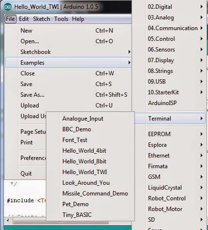
The library can be downloaded here. If you are using Arduino 1.0.5, you can import this be going to the 'Sketch' menu, selecting 'Import Library' and then 'Add Library'. Browse to the downloaded zip file and add it. With older versions, just unzip the 'Terminal' folder and add it to the 'libraries' folder in your Arduino directory.
As previously, I've had fun writing a few samples. The mock up BBC start screen now looks better in 40 character mode which more closely matches mode 7 (the previous demo was more like mode 0). The homage to Look Around You also works better in 40 character mode.
I've updated the Hello World samples to show the character set in a more useful way, and added spinning characters in the corners.
The new version of the video processor supports multiple different styles, on a per line basis, there is now a demo showing off the various options.
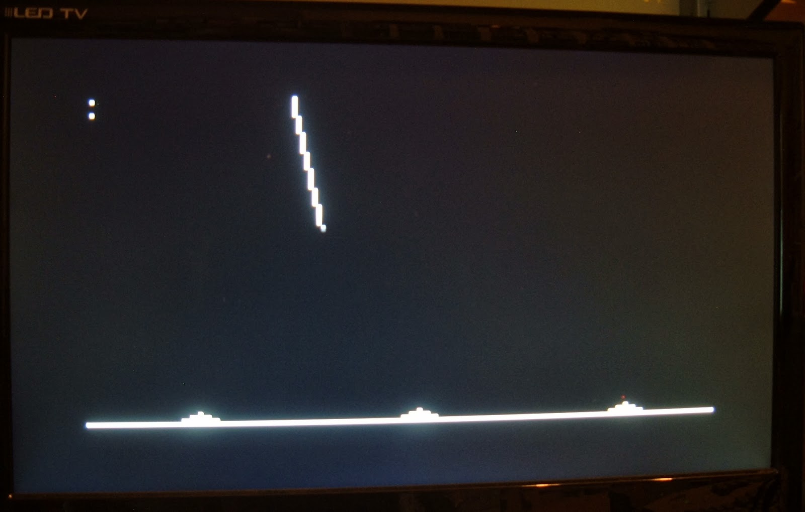
The new version also brings graphics mode. The ability to address the display as 160x100 pixels with set pixel and clear pixel commands. I've extended this functionality in the library and added functions to draw lines, boxes and circles.
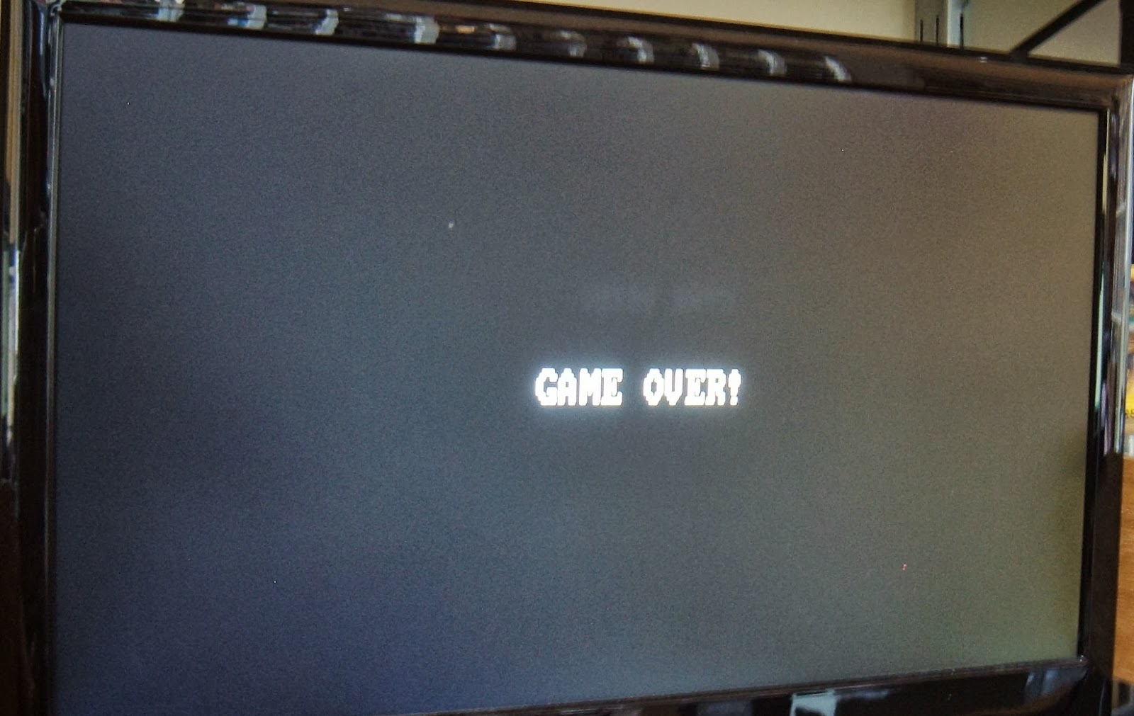
When testing the line drawing, it reminded me of the old Missile Command games, so I mocked up a demo of that. This is just a simulation, it just fires at the bases and loops around after firing 5 shots. I don't know if there is enough to be able to make that a playable game, maybe.

Sunday, 22 September 2013

Arduino 80x25 Text TV Out Shield and Library

This is an old post, preserved for reference.
The products and services mentioned within are no longer available.

[Update: Please see the new version which supports multiple fonts and 'medium resolution' graphics]

I've update the library used to generate 80x25 characters of text output to a TV or video monitor on and Arduino. This now uses the latest update to Grant Searles code which incorporates his 4-bit and 8-bit modes and the I2C version I had previously forked the library to add has now been rolled into the main library.
I've also build a shield to make using this even easier. This is currently a prototype, if there is any interest in this, I could put together a PCB version.
Grant is currently expanding the capabilities and adding as many character options as we can think of, soon it will support 80 character or 40 character text, single or double line height and a choice of two fonts. That's what all the DIP switches are for, to select the initial state of the display. Once the video processor is on the shield, That leaves you free to do what you want with the rest of the Arduino.

Monday, 16 September 2013

Arduino 80x25 TV Video Output Library I2C Mode

This is an old post, preserved for reference.
The products and services mentioned within are no longer available.

[Update: Please see the new version which supports multiple fonts and 'medium resolution' graphics]

I know I only updated the Arduino 80x25 text tv / video output library yesterday, but whilst I was doing that, a further improvement occurred to me. The original interface was 8 bit parallel with two handshaking lines. This is about as fast as it is going to get, but tricky if you don't have 10 I/O lines available. The recent update was to add 4 bit mode. This effectively halved the speed by splitting the data into two nibbles, but reduced the required I/O pins to 6 (4 bits plus two handshaking). Well. I thought I could take that a step further. It is again fewer pins, now only two are required, but it is slower than the parallel version.
My initial thought was to use serial, but the hardware UART on the is on two pins of port D, and the full 8 bits of port D are required to drive the shift register. Writing the character data to the shift register has to be accomplished in 8 processor instructions, so only a write to a complete 8 bit port is possible. The UART is also interrupt driven, and the timer interrupts need to be maintained for the display updates. The beauty of the 8 bit interface was that it could be polled in the deadspace between timer interrupts.
So what else is available? SPI is an option, but is also interrupt driven. The final thought was the I2C. The ATMega328P TWI (Two Wire Interface) is fully compatible with the Phillips I2C (I Squared C or Inter-Integrated Circuit) bus, and the terms TWI and I2C will be used interchangeably. It allows simple communication with up to 127 devices with only two pins. It can also be polled rather than interrupt driven for exactly the purpose of slow devices, or devices which are busy doing something else.  The two pins required are PC4 and PC5, analogue pins 4 and 5. One of these was used on the parallel version as the shift register load pin. That has been moved to PB1, but means there need to be two different versions of the video processor. Grant Searle's original with 4bit or 8bit parallel interface, and the new I2C only version.
The documentation on implementing an I2C slave was a bit minimal, most of the examples covering only master mode. But though it took quite a while to get it working, the actual code changes to the video processor boiled down to be quite minimal. Now it initialises itself as an I2C slave as address 1 (this can be changed in the code if required). In the main loop, instead of looking for new parallel data, it checks the I2C interface and reads new data if there is any. The changes at the Arduino end are a bit more complicated. The Wire library is used to setup the Arduino as a master device and data is sent though to the terminal. The wire library has a limit of 32 byte packets, so I split larger strings up before sending. I also found problems with packets of only a few bytes. This could be an issue in my code or the wire library, I'm not sure. I had to add a small (50uS) delay after sending small packets or it can loose every other packet sometimes. Below is a screenshot from a debug version which just printed the value of the character it received, it was being sent a sequence 00, 01, 02, 03 etc. up to FF and back to 00. As you can see, it starts ok, but where is 75, 77, 79 etc.? The delay seems to fix this and doesn't slow it down too much. 50uS may be a lot in terms of 16MHz processor clocks, but if all you're doing is echoing characters being typed, it's perfectly acceptable. As with the 4-bit mods, it can still update the screen much faster than it can be read.
The library has been updated to support I2C mode, and there is now a Hello World I2C sample with the character set in I2C mode. This was a good test as the characters and the spaces between are all sent individually, where as the two 80 character lines are sent as single text lines, and there are various control codes to position the slashes at the corners.
The new library can be downloaded here. This zip file includes the source and hex files and source for both versions of the video processor, and an updated version of the library which supports I2C mode.
It is possible to use the Video Processor in I2C mode without the library, just using the wire library.
  #include <Wire.h>

  void setup()
  {
    Wire.begin();
  
    Wire.beginTransmission(0x01);
    Wire.write("Hello, World!");
    Wire.endTransmission();
  }

  void loop()
  {
    // your code
  }
If you go for just the Wire library, you will need to deal with the issues of the 32 byte Wire buffer and small packets.

Sunday, 15 September 2013

Arduino 80x25 TV Video Output Library V0.2

This is an old post, preserved for reference.
The products and services mentioned within are no longer available.

[Update: Please see the new version which supports multiple fonts and 'medium resolution' graphics]

This is an update to my previous version of the 80x25 tv video output library for Arduino. Grant Searle has updated his video processor code (upon which this is based), to support 4 bit mode. This reduces the number of I/O pins required from 10 down to 6 (4 bits and 2 control lines). See his page for further information on that.
As before, all you need to do is download my 80x25 TV Video Output Library for Arduino library, and extract it into the libraries folder inside you arduino projects folder. The choice of the 6 pins is up to you, here is how it is wired in the code examples in the library.
There are two 10K resistors which control the mode of the video processor. R 4bit is there to set 4 bit mode. R NTSC can be used to set NTSC output mode. Omit R NTSC for PAL mode.
Note, this time I am following Grant's advice and using a 74HCT166. Although the 165 I used last time works, the 166 is preferable due to it's fully synchronous output. The HCT version is also preferable to the LS version. Compare the gaps between the zeroes. Firstly, a 74LS165:
Then a 74HC165
And finally a 74LS166
As you can see, the sharpness is improved. The variation in brightness is due to poor photographic skills on my part.
Although 4 bit mode is half as fast as 8 bit mode, it can still update the display considerably faster that you can read. One of the examples in the library I have provided reads the 6 analogue inputs and displays a binary representation of their value. It does this as fast as it can and continues to send data to the display, which scrolls up as the data appears. This is a good example of using this sort of output for debugging purposes.

Friday, 6 September 2013

Arduino 80x25 TV Video Output Library

This is an old post, preserved for reference.
The products and services mentioned within are no longer available.

[Update: Please see the new version which supports multiple fonts and 'medium resolution' graphics]

Arduino TV Out has been around for a while, but you can't get many characters on the screen and uses a lot of the Arduino's resource. This is a library which will let you generate an 80x25 text screen on a TV or monitor from an Ardiuno. Well I say from an Arduino, it's more like two Arduinos, or to be precise, an Arduino and a second ATMega328P as a video processor, and one additional TTL chip.
The video processing work is all done by the second ATMega328P, the video processor. This leaves the main processor (the ATMega328P on the Arduino) to do whatever you like. There is a simple 8 bit data transfer whenever a new character is to be added to the display, in a similar way to driving an LCD display. The concept comes from Grant Searles Monitor and Keyboard interface, itself an update of code by Daryl Rictor (40x25 display using an ATmega8). The code in the second chip is unmodified from Grant's (download from his page above). I've completely rewritten the Arduino code, now in the form of a library to make it easier to use.

           Shift Register --> Char Data
               /                   \ 
Arduino <==> Video Processor        + ==> Video
               \                   /
                   Composite Sync

The idea is basically this, the Arduino (the first ATMega328P) has an 8 bit output port and two control lines. This interfaces to the video processor (the second ATMega328P). This has an 8 bit output port and 1 control line which is fed to a 74LS165 or 74HCT166 shift register (the pinouts are different, but they can both provide the necessary functionality, you may have more luck finding the 165) [Update: the 166 is preferable, and the HCT version should be used if possible]. The output of the shift register is the character video output data. There is also a composite sync is output from video processor. The composite sync and video data are combined via two resistors and this forms the composite video output. This composite video output is suitable to drive a modern LCD TV or an old CRT TV or monitor.
OK, so how do you do it? Well first you need to program the second microcontroller. This is written in assembler and does not use the Arduino bootloader, so needs to be uploaded via a programmer. There are many options, use an external programmer, use something like the USBTiny ISP to program in circuit, or use the Ardunio as an ISP.
If using an external programmer, such as the MiniPro, select ATMega328P, set the fuses to E6 D9 FF and select Grant's SBCVideo.hex file.
Alternatively, since there is already going to be an Arduino and a second ATMega328P, Arduino as ISP can be used. Wire up the circuit as per the Arduino as ISP demo (leave some space for the 74LS165). Here is an excellent tutorial on Arduino as ISP, and more info on avrdude.
Once built up, you can test it in the Arduino environment by selecting Arduino As ISP from the Programmer menu, As a test, load up the 'blink' example and use 'Upload using Programmer' to upload it. If all is well, the LED on digital pin 13 will blink. This is running from the second ATMega328P (their pin 13's are connected together). You can easily test this if you remove the wire and see it stop flashing. If it keeps flashing, you've reporgrammed the Arduino instead, try again. The fuses need to be set, and a hex file uploaded. This cannot be done from the Arduino environment, so you need to use avrdude on the command line to program the device. The commands required are as follows (change the com port as necessary)

  1. avrdude -P COM3 -b 19200 -c avrisp -p m328p -n
  2. avrdude -P COM3 -b 19200 -c avrisp -p m328p -U lfuse:w:0xe6:m
  3. avrdude -P COM3 -b 19200 -c avrisp -p m328p -U hfuse:w:0xd9:m
  4. avrdude -P COM3 -b 19200 -c avrisp -p m328p -U efuse:w:0xff:m
  5. avrdude -P COM3 -b 19200 -c avrisp -p m328p -U flash:w:SBCVideo.hex

Once the video processor is programmed, wire it up as per the circuit diagram. The pins on the video processor should remain the same (unless you want to modify the source). The pins on the Arduino end can be any. I chose the nearest ones. The only exception was choosing digital pin 13 as the Ack pin. This just shows activity on the LED on the Arduino for diagnostic purposes. The pin connections are:

  • Video Data In 0: Arduino D12 - ATMega328P pin 15
  • Video Data In 1: Arduino D11 - ATMega328P pin 16
  • Video Data In 2: Arduino D10 - ATMega328P pin 17
  • Video Data In 3: Arduino D9 - ATMega328P pin 18
  • Video Data In 4: Arduino D8 - ATMega328P pin 19 
  • Video Data In 5: Arduino D7 - ATMega328P pin 23 
  • Video Data In 6: Arduino D6 - ATMega328P pin 24 
  • Video Data In 7: Arduino D5 - ATMega328P pin 25
  • Video Available: Arduino D4 - ATMega328P pin 26 
  • Video Ack: Arduino D13 - ATMega328P pin 27
  • Reset: Arduino Reset - ATMega328P pin 1
  • 16 MHz Crystal to ATMega328P pins 9 and 10
  • 22pf capacitors from ATMega328P pins 9 and 10 to GND
  • Video Data Out 0: ATMega328P pin 2 - 74LS165 pin 11
  • Video Data Out 1: ATMega328P pin 3 - 74LS165 pin 12
  • Video Data Out 2: ATMega328P pin 4 - 74LS165 pin 13
  • Video Data Out 3: ATMega328P pin 5 - 74LS165 pin 14
  • Video Data Out 4: ATMega328P pin 6 - 74LS165 pin 3
  • Video Data Out 5: ATMega328P pin 11 - 74LS165 pin 4
  • Video Data Out 6: ATMega328P pin 12 - 74LS165 pin 5
  • Video Data Out 7: ATMega328P pin 13 - 74LS165 pin 6
  • Shift Register Load: ATMega328P pin 28 - 74LS165 pin 1
  • Shift Register Clock 1: ATMega328P pin 10 - 74LS165 pin 2
  • Shift Register Clock 2: GND - Shift Register pin 15
  • Shift Register Serial Load: GND - Shift Register 10
  • Composite Sync Out: ATMega328P pin 14 via 1K to Composite Video Out
  • Video Out: 74LS165 pin 9 via 470R resistor to Composite Video Out

The breadboard wiring is as follows:
It should probably look neater than this.
Once that is built, you can get on with the coding. Download the Terminal library, unzip it and copy the 'terminal' folder into the library folder in your Arduino workspace. You should then be able to include the terminal.h file in your projects.
There are a number of examples provided, these show using the library to generate things like a BBC Micro startup screen.
Or from a Commodore Pet  (notice different cursor options are available):
Since the work is now being done by the video processor, it leaves most of the Arduino free to do something more useful. For example, with a slight modification to Mike Field's Tiny BASIC, it can use the terminal as an output.
The input is from the serial terminal. It is left as an exercise for the reader to provide a keyboard of some sort. The I2C, and half of the input pins are still available, and SPI could be freed up so there are lots of choices.
Since the sync and video are available separately, it can even drive something odd like an Amstrad GT 65 green screen monitor which has separate sync and video inputs
The sync and video are wired to the monitor inputs directly. The the resistors can be removed if the composite video is not required.
The whole reason for doing all this is to drive a Commodore Pet monitor, as part of my Pet Project.
However, that turned out to be a lot more complicated. More on that later....