This is an old post, preserved for reference.
The products and services mentioned within are no longer available.
This is a preview of an upcoming project. Not sure if the name will stick, but at the moment it's called PET Exerciser (
UPDATE: it didn't, it's now called 6502 Diagnostics). This started when I was repairing a few PETs and was using a NOP generator. This idea of these is the hard wire the NOP instruction onto the processor databus, the end result of that is it just steps through all the addresses sequentially, continually. That is useful to check address decoding, and see if chip enable pins are pulsing in the right way. The trouble is the 1MHz 6502 based NOP generator is a bit slow to check high address bits on a scope (at least one without digital storage), but too fast to check by eye.

I got to thinking, could I adjust the clock rate fed to the 6502 to get the pulses into a more usable range? Before I started looking at that, I thought that it would be easier to just bypass the 6502 all together and use a couple of 8 bit counters to cycle through all the address bus at whatever speed I chose. I did look at a few options for that, but it was going to be a bit messy as it would have ended up with 4 x 4 bit counters and a pulse generator, which was maybe going to be an 8 pin microcontroller. I then thought I could just use a microcontroller. And lo the PET
exerciser diagnostics was born.
I then got to thinking, if I had a few more pins on the microcontroller, I could access the databus and some of the control signals as well. Hmm. interesting. The prototype doesn't look as neat as that final PCB will.
Under that mass of wires is a Commodore PET, and on the breadboard is a micrcontroller, the DIP version of the one I will use on the final board. The microcontroller is connected to most of the pins in the 6502 socket. There isn't an actual 6502 involved any more. Before I got around to writing the code for the NOP generator. I was interested to see if I could actually drive the PET hardware to do anything interesting.

This is the first test was a screen of incrementing characters, but as I got the hang of writing the PET video RAM, that quickly grew into a character table. If nothing else than to help me work out what characters to write the the video RAM to show on the screen - it's PETSCII, not ASCII. Since I can now write to RAM, I can also poke things, and one useful poke on the PET is to change character sets from business mode (with uppercase and lowercase letters) to graphics mode (without lowercase but more symbols. This sets CA2 on the VIA which controls the high address line on the character ROM.

Here you can see the PET board I was testing has a faulty character ROM, some of the symbols are not displaying correctly in graphics mode. OK, this is proving rather interesting and should be very useful. What next? Well, let's test the RAM. I'm currently working on a 2001 board, so I've only set it to test the first 8K. I've split it into 1K blocks and tested by bit to help narrow down the faults.
The test algorithm I'm using is fairly simple, I'm just poking various values and reading back. I'm recording any bits that are different from the values written, and here it has picked up 2 errors on one RAM chip. This matches what BASIC was showing when the PET was running, it only detected the first 1K of RAM, so was showing around 800 bytes free. I've removed the chip I think it is, and retested.
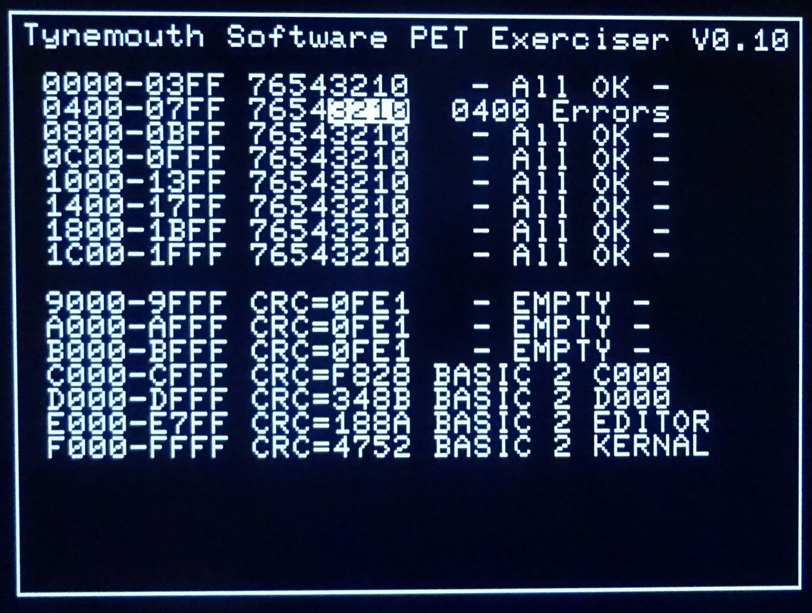
Good, it's showing 400 errors (that's 400 hex, 1024 decimal), all in the lower nibble, which is exactly the area served by the 2114 chip removed. I tried to lay the screen out to match the orientation of the chips, so the second row of 2114 chips, right hand side is the culprit.
I replaced the chip and retested and it's now fine, and when I return this to 6502 control, it should detect all 8K of RAM again. The TMS2114L-20NL I have used there isn't an exact replacement for the TMS4045-45NL, but is enough to prove the point whilst I try to locate something better. I'll probably use one of the pair that are the video RAM, and replace both of those with faster 2114 chips.
You can see where I was also starting to test the ROMs. I've gone for a simple 16 bit checksum of the ROMs, and that seems to be working consistently. I've added a lookup table of CRC codes with descriptions for known good ROMs. I've got it plugged into one of my 6502 ROM/RAM boards for testing, so I have been able to get CRCs for most of the standard ROM sets already. This is a good way to identify faulty ROMs.
Here some of the 6540 ROM chips are working (I've given the chip numbers of the good ones), but the others are coming back with different CRCs. The CRCs have also changed on those as I have repeated the test, so I guess they are faulty, or since it is only the x000 ones that are working, there may be a problem with the BA11 line that controls the x800 ones. More testing required.
I've added in a test for video RAM before the screen is drawn, and inserted the results into the memory map. I'm testing the full 2K region, but the second 1K is a mirror of the first, apart from 80 column systems. I've also expanded the address ranges to test the 32K and 4K ROM sets on a 4032 system. These two modes may be a different build, jumper selectable, or maybe by a menu?

I'm getting a bit carried away, there are so many possibilities here, and I think this is going to turn into a very useful piece of kit. There any many more things I plan to add, such as scanning the keyboard to test the keyboard, and also to control a menu system to cycle between various tests. I can also add testing for datasettes, IEEE-488 drives and even printers. I need to look into initialising the CRTC on later PETs so they can be used as well, and also reformat the screen for 80 column use. I could even include a simple BASIC interpreter....maybe not. It would also suit many other 6502 based machines, including the VIC20, BBC micro, and maybe some of the Atari 400/800 series. Anywhere there is a 6502 processor and a display that I can work out how to drive.

So just to recap, this is being generated on a real PET, with the PET exerciser in the 6502 socket. It's a microcontroller with it's own ROM and RAM. No 6502 code is executed. No actual 6502 is used. No PETs were harmed in the testing of this product.
UPDATE: I've decided to go with PET diagnostics. I have also added a reset button and disconnected that from the onboard reset, instead monitoring that to show faults with onboard reset circuits.
UPDATE 2: I've changed the board to just 6502 diagnostics, as I will be looking at other systems to use (KIM-1, VIC20, BBC etc.), I'll keep PET diagnostics as the on screen title for the PET version of the software. I've removed the reset switch, but kept the reset monitoring. I've added some DIP switches to allow screen mode to be set and maybe some other options. The PCBs have now been ordered.
UPDATE 3: The boards have arrived, but the PCB manufacturer has managed to mess up my design and rotated the ground pad of the main IC to short out several of the pins, including the +5V rail. This is what I had designed:
This is what arrived:
Now waiting for a second batch.
UPDATE 4: Still waiting for the boards, in the mean time, I've redesigned it a bit, with a bigger microcontroller. This now appears as a USB device and shows status in a serial terminal. This also has some analogue inputs so I can check the rise time of the power and reset pins (to check problems like I had with the
Oric 1 repair recently).
UPDATE 5: I'll write this up properly once I have had time to do further testing, but the V1.1 boards have now arrived, with no pads rotated as far as I can see. The first one is now built up and being tested.
This is how it would be used, plugged into the CPU socket of a Commodore PET.
UPDATE 6:
More on the
testing of these new board.
UPDATE 7:
The new boards
are available now.