Update
I have reopened my Tindie store and have new batches of Minstrel 2 and 3 kits, for ZX81 case or standalone with keyboard, and ZXpand microSD card interface.
From there I can ship worldwide.
I will slowly be moving things over there from my SellMyRetro store, so if there is anything that you want, let me know and I'll add it.
Minstrel 2
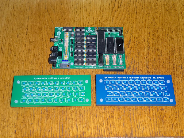
The Minstrel 2 is a ZX80 compatible Z80 based computer with 16K of RAM and jumper selectable 4K integer BASIC or 8K floating point BASIC. The later is compatible with the ZX81 with the exception of SLOW mode, which is not supported by the ZX80 hardware (which mean most ZX81 games will not run).

The Minstrel 2 and 3 main boards are ZX81 sized, so can be fitted in a ZX81 case as a drop in replacement.

The detachable tact switch keyboard is optionally available if you want to run it stand alone, and can also be shared between the Minstrel 2 and 3.

I have recently started making more use of the detachable element to swap between versions with keywords for the 4K and 8K BASIC on the Minstrel 2.

To that end, I am now offering that in built and kit form with dual keyboards that you can swap as easily as you change the jumper from the 4K ROM to 8K ROM.
Minstrel 2 at Tindie:
- Full kit (or built) with keyboard - https://www.tindie.com/products/tynemouth/minstrel-2-with-keyboard-z80-based-zx80-kit/
- Full kit (or built) for ZX81 case - https://www.tindie.com/products/tynemouth/minstrel-2-for-zx81-case-z80-based-zx80-kit/
Minstrel 2 at Z80kits.com:
- Full kit with or without keyboard - https://z80kits.com/shop/tynemouth-minstrel-2/
Minstrel 2 on Sell My Retro:
- Built and tested with dual keyboard - https://www.sellmyretro.com/offer/details/63942
- Built and tested for ZX81 case - https://www.sellmyretro.com/offer/details/62386
- Full kit with dual keyboard - https://www.sellmyretro.com/offer/details/63946
- Full kit with no keyboard - https://www.sellmyretro.com/offer/details/63729
- Keyboard kit with 4K keywords - https://www.sellmyretro.com/offer/details/63944
- Keyboard kit with 8K keywords - https://www.sellmyretro.com/offer/details/63943
- PCB only - https://www.sellmyretro.com/offer/details/62001
- Keyboard PCB set 4K keywords - https://www.sellmyretro.com/offer/details/61984
- Keyboard PCB set 8K keyboard - https://www.sellmyretro.com/offer/details/62033
- Keyboard PCB no overlay - https://www.sellmyretro.com/offer/details/61986
Minstrel 3
The Minstrel 3 is a ZX81 compatible Z80 based computer with 32K of RAM and 8K floating point BASIC. It does support slow mode, and several high resolution mechanisms, so the majority of ZX81 games will run fine.

As with the Minstrel 2, this is available in a variety of forms, including ZX81 case and standalone with tact switch keyboard.

Minstrel 3 at Tindie:
- Full kit (or built) with keyboard and ZXpand - https://www.tindie.com/products/tynemouth/minstrel-3-keyboard-zxpand-z80-based-zx81-kit/
- Full kit (or built) with keyboard - https://www.tindie.com/products/tynemouth/minstrel-3-with-keyboard-z80-based-zx81-kit/
- Full kit (or built) for ZX81 case - https://www.tindie.com/products/tynemouth/minstrel-3-for-zx81-case-z80-based-zx81-kit/
Minstrel 3 at Z80kits.com:
- Full kit with or without keyboard - https://z80kits.com/shop/tynemouth-minstrel-3/
Minstrel 3 on Sell My Retro:
- Built and tested with keyboard - https://www.sellmyretro.com/offer/details/63941
- Built and tested for ZX81 case - https://www.sellmyretro.com/offer/details/63727
- Full kit with keyboard - https://www.sellmyretro.com/offer/details/63947
- Full kit with no keyboard - https://www.sellmyretro.com/offer/details/62147
- Keyboard kit with 8K keywords - https://www.sellmyretro.com/offer/details/63943
- PCB only - https://www.sellmyretro.com/offer/details/39921
- Keyboard PCB set - https://www.sellmyretro.com/offer/details/62033
- Keyboard PCB no overlay - https://www.sellmyretro.com/offer/details/61986
Minstrel ZXpand
Add an SD card and joystick to your Minstrel 3. (no, this will not work on a real ZX81 before anyone asks)

Minstrel ZXpand on Sell My Retro:
- Built and tested - https://www.sellmyretro.com/offer/details/64261
- Full kit - https://www.sellmyretro.com/offer/details/62149
Micro ZXpand Minstrel

This is a cut down version of the Minstrel ZXpand, based on ZXpand by Charlie Robson (sirmorris). It is only suitable for more recent Minstrel 3 boards with the pads by the edge connector (V3.5.5 and V3.5.8). I will, as is customary, state this is not suitable for use with a ZX81, but can now add also unsuitable for Minstrel 2 and older Minstrel 3 boards, and it will not fit inside a ZX81 case (there are pillars in the way).
Minstrel Expansion Bus
This is a four slot backplane with the same 2x23 pin header as found on recent Minstrel 2 and 3 boards. With optional power input and 5V regulation and a rear pass through connector. Can be plugged into a Minstrel 2, Minstrel 3 or a real ZX81 (which can be powerd from the DC power jack, avoiding the rather poor 3.5mm jack onboard).

Available in assembled, kit and PCB only versions. If ordering assembled, let me know which options you would like.
- https://www.sellmyretro.com/offer/details/64325
- https://www.sellmyretro.com/offer/details/64326
- https://www.sellmyretro.com/offer/details/64327
But what can you plug in?

Well, how about a Kempston compatible joystick module.
Minstrel Joystick
This is a simple Kempston compatible joystick interface, but fully decoded at address 31 (0x1F).

Also available in assembled, kit and PCB only versions.
- https://www.sellmyretro.com/offer/details/64329
- https://www.sellmyretro.com/offer/details/64328
- https://www.sellmyretro.com/offer/details/64330
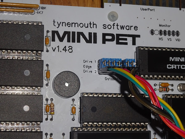
Mini PET A
All Mini PET kits are now sold out. Sorry.
But wait - watch this space for news about the Mini PET II coming soon.
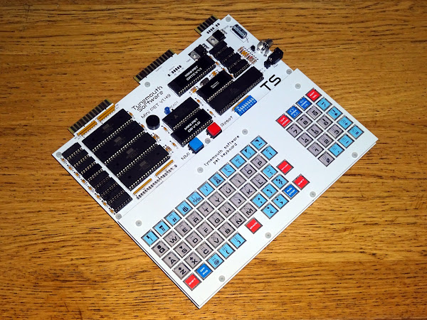
The Mini PET is a Commodore PET compatible 6502 based computer with 32K of RAM and a choice of PET BASIC 1,2 or 4, or Mini PET BASIC 4.0.
This is the stand alone version that can be used with one of my keyboards or another aftermarket PET keyboard (normal / graphics layout recommended for better compatibility than the business keyboard).
Mini PET A on SellMyRetro
Built and Tested with Deluxe Keyboard - https://www.sellmyretro.com/offer/details/63877Full kit with deluxe keyboard - https://www.sellmyretro.com/offer/details/63951Full kit with no keyboard - https://www.sellmyretro.com/offer/details/63950Deluxe Keyboard kit - https://www.sellmyretro.com/offer/details/63949Deluxe Keyboard PCB set - https://www.sellmyretro.com/offer/details/62022Tact switch Keyboard PCB only - https://www.sellmyretro.com/offer/details/62020
Mini PET B
The B variant is designed as a drop in replacement for a PET motherboard. No keyboard options are provided, as you are expected to use the PETs original keyboard.

In addition to the DC power and composite video output of the A, the Mini PET B can use the PET power supply (5 pin or 9 pin) and drive a PET 9" or 12" monitor.

Mini PET B at SellMyRetro:
Built and tested - https://www.sellmyretro.com/offer/details/63875Full Kit - https://www.sellmyretro.com/offer/details/63876
Mini PET Extras
I have also listed for the first time a few extra boards I designed to go with the Mini PET.
SD2PET Power TAP
This is an adapter which can be plugged into the rear datasette port on a Commodore PET or Mini PET to provide power to an SD2PET whilst still providing a connection for a datasette drive.

SD2PET power tap on SellMyRetro:
- Assembled - https://www.sellmyretro.com/offer/details/63953
- PCB only - https://www.sellmyretro.com/offer/details/63952
PET Datasette interface.
This is a PCB which provides an interface to a Commodore datasette edge connector. The internal connection is a 6 way 0.1" connector (7 pin with 1 pin missing for polarisation).

This can be used to add the second datasette port to a Mini PET kit A, or for various extending one of the Mini PET datasette ports or for any other datasette interfacing projects.
PET datasette interface PCB on SellMyRetro:
PET Power Interface
Finally, something which was used with the original versions of the Mini PET. I later designed the B kit which integrated this board into the main board. It may still be useful for other things. It can be used to tap 9V DC from a PET power supply to power a Mini PET or other project inside a PET case.

PET Power Interface on SellMyRetro:
- Full Kit - https://www.sellmyretro.com/offer/details/63958
- PCB Only - https://www.sellmyretro.com/offer/details/63956
PET Dual Userport Joystick
I have recently revived the PET dual userport joystick, as a through hole version, available as PCB, kit or assembled.

PET Dual Userport Joystick on SellMyRetro:
- Assembled - https://www.sellmyretro.com/offer/details/64260
- Full Kit - https://www.sellmyretro.com/offer/details/64257
- PCB Only - https://www.sellmyretro.com/offer/details/64256
Also available with a piezo for PET 2001 and 2001N owners that do not have an internal piezo on userport CB2.

As before, Assembled, Kit and PCB versions.
- Assembled - https://www.sellmyretro.com/offer/details/64319
- Full Kit - https://www.sellmyretro.com/offer/details/64323
- PCB Only -https://www.sellmyretro.com/offer/details/64318
Patreon
You can support me via Patreon, and get access to advance previews of posts like this and behind the scenes updates. These are often in more detail than I can fit in here, and some of these posts contain bits from several Patreon posts.
This also includes access to my Patreon only Discord server for even more regular updates. I have been spamming the Discord with these new listings as they have been added over the last few weeks, to make sure they had first chance to get some of these things.
https://www.patreon.com/tynemouthsoftware