Tuesday 18 August 2015

Atari ST USB keyboard

I worked out the circuit for this a long time ago, but I've never actually built an Atari ST USB keyboard before. The main reason being the size of the case. If you have an ST case with only the keyboard and a USB keyboard controller in, it still takes up quite a bit of desk space, so I presumed no one would want one. The same with the Commodore Amiga.
Then someone asked for one, so here it is. The request was for a 1040ST, and I found a suitable candidate, this one looked quite nice, but actually appeared to be a 520STFM with a 1040STE badge? It also had a memory fault, and will serve as a supply of spares for another 1040STE I'm currently repairing.
The Atari ST keyboard has an integrated keyboard controller and two 9 way D joystick ports. This connects to the main board via a serial connection.
These are accessed from under the keyboard. A common source of faults on ST's is bad contacts on these, and this is caused by cracked solder joints due to mechanical damage. If you've ever had to wiggle a plug to get something like this to work, it's probably because of cracked joints like this. Wiggling the plugs just makes it worse as it stresses the other pins and can cause problems with them as well eventually.
So first task was to strip down the keyboard, clean all the contacts and fix the cracked joints on those connectors. I find the best way to deal with those is to effectively desolder them, removing all the existing solder, then resolder them with fresh solder.
The cable from the keyboard has an 8 way 0.1" on the end. To make wiring to the controller easier, I made a mating cable with the pin version of the Harwin M20 connectors.
The connections on that cable are as follows, the baud rate looks odd (7812.5), but this is a direct divisor of 1MHz (7812.5*128=1MHz), and also the 16MHz clock I was using.
  1. Ground
  2. Not connected (polarising pin)
  3. Floppy LED (active low)
  4. +5V power to keyboard
  5. Serial data from the keyboard (7812.5 baud, 8N1)
  6. Serial data to the keyboard
  7. Reset (active low)
  8. Ground
The cable was wired to a suitable USB keyboard controller, one of my smaller ones as few pins were required. This may have been a slight mistake as the ATmega8U2 on there ended up 98% full. I almost had to swap it out for an ATmega16U2.
The USB keyboard controller was fixed in the case so the connector could be accessed through an existing hole.
With that in place, it was just a case of writing the software. There are various documents online referring to the keyboard protocol. It turned out to be reasonably simple, Start by pulsing the reset line low, then there was an initial bit of communication to tell it to switch into a mode where it would report all keypresses and joystick movements. It is possible to configure it to work with one joystick and one mouse, rather than two joysticks, but I thought this would be more useful. Leave the ST mice for use with STs.
It was then just a case of reverse engineering what came back from the keyboard, each keypress and key release are sent as single bytes, and joystick movement is two bytes. These were translated into USB keyboard keypresses. I had to create a matrix of currently pressed keys and update that whenever anything came from the keyboard. There are two LEDs, one power which I left as that, and the other showed disk access, this now shows caps lock status.
When plugged into a PC or Mac or tablet, this appears as a USB keyboard and two USB joysticks, so can be used anywhere those could be used, including of course Atari ST emulators.
There is quite a lot of space left inside, enough for a Raspberry Pi or something like the Intel NUC I used in the Atari 800XL PC,
These and other similar USB keyboard controllers are available from my Tindie store.

Update:
See also a whole Intel i7 based PC installed in an Atari ST, using this adapter.

Update 2:
The current builds of these are a little tidied up over the original, the wires are now on the back of the board.
The yellow wire is no longer connected as it is unused, so there are two spare pins at the end.

Update 3:
A new dedicated version of the Atari ST USB keyboard controller is available from my Tindie Store.


2023 Update

USB Keyboard Controller Kits are available from my Sell My Retro store:

Friday 7 August 2015

Commodore PET 2001-8 Repair - Part 1

This is an old post, preserved for reference.
The products and services mentioned within are no longer available.

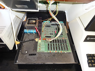
Look what's just arrived, my latest acquisition, a Commodore PET 2001-8.
Looks in very good condition so far, and quite a low serial number 8411?
It still has the screws holding the lid closed, they often tend to be missing.
I've been after one of these for a while, quite an iconic piece of kit. The design dates back to 1977, although this one is from late 1978.
One of the earliest home computers, fighting for it's place with the TRS80 - both of which seem to have been forgotten by Apple fans. But neither of those have bonet props, so the PET wins for me.
These first PETs have chiclet style keyboards, the same layout as the later graphic keyboards, and the built in datasette drive.
Inside it was very dusty, doesn't look to have been touched for a while. The gap in the dust is where the keyboard cable was resting.
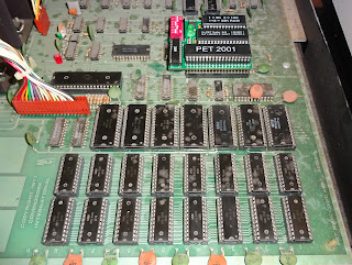
The large number of chips at the bottom show this is an early one. The 2001-8 comes with 8K of RAM and 7K of ROM. There were a few different versions of the 2001-8, some had 6550 RAM, some had 2114 RAM. Some had 6540 ROMs, and some 2716 compatible ROMs. This is the earlier combination, 6550s and 6540s.
That's going to be fun as replacements for these are very difficult to find, as I think they were only used in the PET.
The rest of the board has the CPU, I/O and video circuits, along with another 6540 character ROM and two more 6550s as the screen RAM. This looks rather random compared to the later more regimented board designs. All looks reasonable inside, time to turn it on.
It does a few different things on power on. Most of the time it boot up, then locks up, often with a few characters appearing on the screen first. And no, there isn't a key stuck down, it does the same with the keyboard unplugged, but thanks for the suggestion.
Other times you get the traditional garbage on the screen. This is sometimes misunderstood. When the system powers on, the contents of the screen RAM is random, and before the software in ROM is running, the video circuits do their job and show this on the CRT. It is always there, but usually disappears before the monitor warms up. Once the editor ROM starts up, it clears the screen and puts up the traditional '*** COMMODORE BASIC ***' prompt. So in this case, it hasn't run long enough to clear the screen.
Time for one of my ROM/RAM boards, but the 2001 boards have unusual chip sockets. They have extended sides so the make contact with the pins all the way up side. This means the usual turned pin headers I use on the ROM/RAM board do not fit very well.
I've built up a special ROM/RAM board with different pins, using the bottom half of some stackable headers.
This make good contact with the socket. I've loaded this up with various versions of BASIC suitable for non CRTC PETs like this 2001.
With the ROM/RAM board taking over, everything seems to be fine.
This ran various memory and system tests for several hours and all was well, so all the rest of the board is OK, the problem is the ROM or the RAM.
Leaving the replacement ROM enabled, but boing back to the original RAM, also ran for an hour or so with no problems. That's a relief, all the 6550s are OK.
So the RAM is OK, but to help isolate the issue, I've switched back to the replacement RAM and then enabled the original ROMs. That failed straight away with the original problem.
So the issue is the ROM, one or more of 7 6540s. Oh dear, however, the ROM contains the original buggy BASIC. You can tell the version from the header line. I count the points at the top of the first symbols. BASIC 1 has asterisks, *** COMMODORE BASIC ***, and BASIC 2 has hash signs ### COMMODORE BASIC ### is BASIC 2. (BASIC 4 actually says it is BASIC 4 *** COMMODORE BASIC 4.0 ***).
So for the moment, I'd be happy to leave the ROM/RAM board in place. I'll probably remove the precious working 6550s and the suspect 6540s. This will also significantly reduce the power consumption, so it should run cooler. The ROM/RAM board can be set to the upgraded 32K and BASIC 4, or can match the original 8K and BASIC 1.
Either way, it can play Space Invaders.
Although if I want to use the PET microSD disk drive to load it, I need BASIC 2 or BASIC 4. But first I will need to fix the IEEE-488 port, as that doesn't appear to be working.
I see a sticker above the datasette port, looks like someone was trying to tap power off it. 5V is still OK, but the transistor is probably gone on the switched 9V as the external datasette port isn't working. So, lots still to do on the 2001. It needs a full strip down and clean up.
The internal datasette drive is basically a normal datasette bolted to the underside of the lid. That is not working, it also needs a clean up and a new belt.
The monitor seems fine, and seeing the PET tester cycle through on the black and white display on this PET reminds me of a project I'm currently working on, here is a sneak peak.
This will be a plug in board which will replace the onboard video circuits to test PETs with display problems. This scans screen RAM to show an exact duplicate of the PETs screen on a 2.2" 240x320 TFT display, even if there is a problem with the onboard video circuits.
That's still a prototype, but I hope to make that available soon as a companion to the ROM/RAM boards.

Update:

The pins fitted to the current stock of boards suit all socket types, so the long pins are no longer required.

These boards are available to buy from my Tindie Store, alongside the new smaller PET ROM RAM board.


2022 Update: The LCD project never happened as I wasn't able to get a reliable supply of good LCDs. But the principles used in it led to the development of the Mini PET.
The redesigned small version of the PET ROM/RAM boards are still available from  TFW8b.com 

Saturday 1 August 2015

Exploding Commodore PET Mains Filters

This is an old post, preserved for reference.
The products and services mentioned within are no longer available.

You occasional find an old computer where the owner has said it blew up. Now you may think this is fanciful and related to the TV and movie attitude that computers blow up when they go wrong, or if you ask them too difficult a question. However, what they are describing is probably the mains filter capacitors failing. You get the same sort of low value capacitors filtering the mains on power supplies on computers like the BBC micro and Apple II.
Over time, these dry up and eventually crack and fill the room with acrid smoke. You can see the progression on the three caps on the bottom row, from three different BBC Micros. The left hand one looks OK, the middle is starting to crack and bulge. The right hand one fell apart whilst being removed. Had that been powered up in that state, it would have gone bang.
I now tend to replace those on BBC micros before I power them up these days, once you've had one or two do that, it's worth the effort. [UPDATE: one of these had gone bang in the ICL One Per Desk I recently repaired]
The Commodore PETs and Commodore disk drives use a separate mains filter, in a can. These too have a tendency to go bang in their old age. This is an 8250, the mains filter is the thin metal can on the side of the transformer.
Here is one that has been removed. It is marked
Funk-Enstorfilter 0.1uF + 2x2500pF XY + 2x100uH 250V ~ 2A
Or a line filter with a 0.1uF capacitor across the mains and a pair of 2500pF capacitors between live and neutral, and a pair of 100uH inductors between input and output. The purpose of these filters is reduce noise generated by the PET being fed onto the mains. This would have been a problem in its day as there were still may simple radios and televisions which did not include power supply regulation, so were sensitive to mains noise, particularly on AM radio. These days there aren't many of those in use, and there is so much noise introduced by switched mode power supplies in computers and phone chargers etc. it's hardly worth the effort.
This is an 8032-SK I'm about to start work on. You can see the red section has been partly pushed out of the can.
There is also evidence of soot on the board beneath. So this presumably exploded at some point the past. The are modern equivalents, but in this case, I am just going to remove it. The mains input goes through this device, so to remove it, it has to be bypassed.
Confusingly, the two blue wires are the inputs to the filter, and the two black wires the outputs. The four terminal blocks on the 8032-SK are normally wired as follows, starting with the nearest the back of the case.
  • black wire, neutral out of filter - blue wire, neutral to transformer
  • blue wire, mains neutral in - blue wire, neutral into filter
  • brown wire, mains live in - blue wire, live into filter
  • yellow/green, mains earth - yellow/green to earth tag

The final black wire out of the filter is live out. This is soldered to the input of the fuse holder. From the fuse holder out it goes to the switch and the switched output is soldered to the wire that feeds live to the transformer. If you're doing anything with these, just take a while to follow it all thorough and don't trust the wire colours. The usual caveats about the potential side effects of death when fiddling with mains should be noted.
A quick way to do with is to remove the three wires from the filter that are screwed into the terminal blocks, and then cut the fourth wire close to the filter can. Take this wire back through the hole in the metalwork and wire it into the third terminal block (live in). The blue wire which is neutral to the transformer need to be moved down to the second terminal block (neutral in).
I prefer to do a slightly better job and desolder all the wires and redo them all in the correct colours and with a bit of heatshrink to better protect the terminals. I do this when I'm doing a full restore, removing everything, cleaning and remaining the metalwork then reassembling. This is is still do be fully cleaned up, but the wiring would be something like this.
I also desolder the transformer live wire and use the now spare screw terminal for that, so that the transformer can be more easily separated.
The 8032-SK now has power again. The monitor works (the signal coming from my 4032), but there is no video out from the main board. So a few more things to be fixed - more on those in a future post.
I normally remove these before they get a chance, but this one has already gone. Time for some investigation. Dremel powered tear down time.
The internals are fixed to the metal can, so the easiest way in was to cut the can off. Inside you can see the full horror show. The ferrite cored inductor at the top and the main capacitor in the middle.
That must have created quite a bit of smoke to push the end cap off, I'm pleased that didn't happen to me.