Tuesday 31 July 2018

ZX Spectrum IO Interface

I have added a new product to my Tindie store, simple IO board for the ZX Spectrum,

This gives 16 digital input lines and 16 digital output lines. I've been meaning to build one of these for a while. For quite a while actually. Back in the 1980s in fact. There were some great computer books in those days from a company called Usborne, and they have made several of those titles available online.
I remember these from the time, and read through many of them from cover to cover, over and over again at the time. Very simple books, but they taught me a lot about BASIC. The programs were generally written for the ZX81, with a list of symbols at the side.
At the end of the listing, these would be expanded and would show you lines that needed to be substituted for Commodore, BBC, TRS80 etc. And it was reading those that then allowed me to go and get some of the other books my local library had like '20 games for your TRS80' and convert them to run on my ZX81 (or my 800XL or my Electron etc.)
Where is this going then? Well, there were a couple of books in that range which talked about interfacing with computers, the 'Usborne Electronic Workshop'. One about building Computer Controlled Robots.
And one about Computer Model Controllers. These told you how to interface switches and lights and motors to your computer, and using those to control a train set and things like that. This was great for BBC, VIC20 and Commodore 64 owners, as they had user ports.
But ZX Spectrum owners didn't have user ports, and had to buy 'a special interface circuit', which I don't remember ever seeing. So I made now one. (and yes, that is my own rather battered copy of 'Computer Model Controllers' from the 1980s)
This plugs into the edge connector and gives two 8 bit input ports, and two 8 bit output ports. More than enough to drive your robot or train set.
This is quite a simple unit, the 16 outputs are 74HCT series output, so can sink or source 6mA, enough for LEDs, but needs a transistor or driver chip if you want to control relays or motors. The inputs are TTL level, and will need pull ups or downs as required. There is no protection on any of these pins, so use with care. Each of the four 10 pin headers has 0V, 5V and the 8 input or output lines.
The ports are at 0x01 and 0x03, and can be accessed from BASIC using the OUT and IN commands.
OUT 1, 255
This will turn all of the pins of output port 1 on (5v).
OUT 3, 0
This will turn all the pins of output port 2 off (0v). The output is latched, and will retain this setting until it is changed.
The input command is
IN 1
So for example,
PRINT IN 1
will print the value read from input port 1
IF IN 3 AND 8 THEN GO TO 100
Will test to see if digital input pin 4 on port 2 is high
The ZX Spectrum IO board is available from my Tindie store as PCB only, kit or fully assembled.

Update:
Yes, this will work on later +2/+3 machines but some adjustment to the port numbers may be necessary to avoid port numbers assigned to the internal hardware on these machines.

2023 Update:

These PCBs are now available from my SellMyRetro store.

Friday 27 July 2018

Commodore PET replacement keyboard update

This is an old post, preserved for reference.
The products and services mentioned within are no longer available.

I have updated my Commodore 2001 PET replacement keyboards, they are now available with black PCB soldermask.
The original version was white, which seemed like a good idea, but when fitted, it highlighted how white my 2001 case wasn't.
The black fits in well with the system label and the datasette drive.
Other than the colour, I have moved the connector out of the keyboard area, more like the original, and plated the mounting holes.
This can be seen when the keyboard is mounted in the PET 2001.
Although it will only fit the case of the 2001 PET with integrated datasette. These can be connected to any PET that has a normal / graphics keyboard, one with 20 keys on the keypad on the right. Useful to test if your keyboard just need cleaning, or if there is a fault with the PET.
It is not suitable for PETs (or rather CBMs) with the business keyboard with 11 keys on the keypad (which is usually the 80 column machines).
For PETs with full size keyboards, you can run the cable out of the front. Or use it on the test bench.
These are available from my Tindie store, as PCBs, kits or assembled and tested units, optionally with a pre-wired ribbon cable.

2022 Update - Some of these are available from my SellMyRetro store - https://www.sellmyretro.com/store/tynemouth-software

Tuesday 24 July 2018

Atari 7800 PAL AV out Composite Video Conversion

This is an old post, preserved for reference.
The products and services mentioned within are no longer available.

Following on from the previous blog post, an AV out composite video conversion of an early NTSC Atari 7800, here we have a later PAL Atari 7800, and I'm going to do the same thing to that.
Although this particular machine is PAL, the board inside looks like it can support PAL or NTSC, with the appropriate jumpers, and suitable Maria, Stella, and ROM chips. (note, there are points marked 'VID' and 'AUD' which do carry these signals presumably as test points, but the video is unbuffered and has the audio subcarrier mixed in, so it's not suitable for direct connection).
There are a few differences in layout to the earlier NTSC only board, but the circuit is basically the same. The main differences are the lack of sockets (other than Maria and the ROM chip), the lack of the side expansion connector (which was never used), and the ROM is 28 pin (and now contains a built in Asteroids game).
Other than those, the rest are PAL versions of the chips in the earlier NTSC machine. This time, the CPU is marked as UM6502, rather than the internal Atari part number, which should be the same as the 6502C, and not the same as the standard 6502 or 65C02.
The TIA chip is very plainly marked, no indication of manufacturer here.
There are some bodge wires on the ROM, also plainly marked.
It is not clear why the bodge wire and resistor are there, but they are there on other 7800 boards as well. There are various jumpers for the ROM chip, including the option to switch the polarity of the chip select from positive (used on the cartridges so it can be wired direct to A12) to negative (as most EPROMs use).
The power input is slightly re-arranged, but still has soft power on capability and that unusual 2 pin power connector.
It seems like they had other ideas in mind when they designed the case.
A 2.1mm DC jack socket fits perfectly in that cutout.
As before, I fitted one, mounted upside down, held in place with a cable tie through the original mounting holes, and wired (centre negative) to the original input pins. This isn't really part of the composite video mod, but I just don't get on with those connectors, so prefer to standardise.
The AV section also has lots of familiar parts.
The parts to be removed are ringed. The same list as usual, different part numbers, but the same circuit.The variable inductor L6 and transistor Q8 are removed to disable the audio subcarrier oscillator. R32, a 6K8 resistor, is removed to separate the audio output from the TIA (but leaving the 1K pullup and 100nF decoupling capacitor in place). R62, a 1K resistor, is removed to separate that section from the point where the video signal is assembled.
The yellow circle shows where the video is picked up from, and the white is the audio. Power is picked up from the supply to the modulator (which is the 5V rail via FB1).
The final thing to remove is the modulator. This version of the PCB is also designed to have a alternative option of a modulator circuit on board, rather than the usual off the shelf canned module. This is protected by masking tape.
With that removed and the board cleaned up, time for the 'Deluxe Composite Video Mod' from The Future Was 8 bit.
This is supplied with a pre-wired detachable cable which just needs to be cut to length depending on application. The video buffer board itself can be mounted to the main PCB using a double sided foam pad or hot melt glue.
The wiring with these new modules is very easy, and picks up on points from the parts that have been removed. Colours should be logical, black for 0V, red for 5V, white for audio, yellow for video.
Just make sure the board is mounted to line up with the hole in the case.
You can then attach the 3.5mm jack to phono plug lead that is supplied with the kit. Here yellow is video, and the red and white jacks both carry the mono audio signal.
Without a cartridge, the 7800 has a built in asteroids game.
This time I do have some 7800 cartridges of the correct region that I can test with. Including this pristine Ms Pac Man cartridge kindly donated by TFW8b #rare.
Which, contrary to it's appearance, works fine.
And of course you can play all your PAL 2600 games.
So that's another system brought up to date with a modern power supply and composite video output.
The 'Deluxe Composite Video Mod' is available from The Future Was 8 bit.

Sunday 15 July 2018

Atari 7800 AV out Composite Video Conversion

This is an old post, preserved for reference.
The products and services mentioned within are no longer available.

After the very successful 2600 and the rather less successful 5200, the next step in the arithmetic progression took Atari to the 7800. Let's see if it is three times as good as the 2600.
This had one important advantage over the 5200, it could play 2600 games. Inside this early NTSC unit, there was a lot in common with the older console.
Under the usual Atari metal can held in place with bent tabs lives the 7800 main board.
There are more chips than the 2600, but it's main three chips are still here.
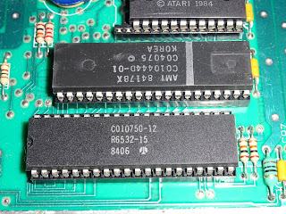
The 6532 RIOT and C010444 TIA are the same chips as used in the 2600. (yes, that is the NTSC TIA, this is an NTSC model, the PAL ones seem thin on the ground these days).
The 6507 CPU on the 2600 is now a full size 6502. Above that is 'Maria', the new sound and video chip.
This is complemented with 2x6116 2K RAM chips and a ROM chip.
This is a 1984 NTSC version of the 7800, which comes with an expansion connector on the side. I don't think anything ever used this, and it quietly disappeared from later versions.
One last thing before I get onto the composite video modification is the power connector. On the 7800, they have gone for a rather unusual 2 pin power connector.
The PSU that came with this NTSC machine was 120V, so I wanted to replace it anyway.
I went for a 2.1mm DC jack, wired for centre negative, like the Spectrum, Commodore 16, and my Minstrel ZX80 clones, so I could use the same power supplies as all of those.
The AV section, is fairly similar to the 2600 Jr, the large red variable inductor will be familiar to anyone that has been inside a 2600.
Here the circuit has two sets of inputs, one from Maria, and one from the TIA. Once those are combined, the composite video feed to the modulator is much the same.
The modification are likewise similar to those I do on 2600 Composite video output modifications.
The parts to be removed are circled on the board.
Seen here on the schematic, removing Q1 and L2 disables the audio carrier oscillator. Removing R3 separates that section from the combined video signal. Removing R5 and R6 disconnects the two audio sources, and provides a point where the two decoupled audio signals can be tapped. And finally, removing the modulator provides a point where the new AV buffer board can be fitted and the power and video connections can be made.
I am using the 'Deluxe Composite Video Mod' from The Future Was 8 bit. My thinking behind giving that board removable connectors again comes in useful. The pre-wired cable just needs to be cut to length and soldered to the board.
The white lead is the audio, and is connected to the bottom of R5 and R6, to get both the TIA and Maria audio. (I left the tinned wire at the end long enough to solder to both pads under the board).
That was nice and easy. The only thing to be wary of is you need to position the AV jack slightly forward of the edge of the board, so that the 3.5mm jack can sit firmly home when the case is refitted.
All that is to do now is to refit the metal RF shield and put it back in the case.
It seems that PAL 7800 cartridges don't work in NTSC 7800 systems, the logo appears, but then it just gives stripes. (could also be Maria or the RAM at fault, I'll retest that when I have some NTSC 7800 cartridge to hand).
I didn't have any NTSC Atari 2600 cartridges either, but I make a board that I could fit an EPROM into, so I burned a few to test, and it's working nicely.
Time for more arduous testing. It's a hard job, but someone has to do it.
This is the 1984 NTSC version on the Atari 7800. The PAL version, and later NTSC version are slightly different boards, but the principals are the same, just locate those components and fit the board in an appropriate location. - see the same conversion on a later PAL Atari 7800.
The 'Deluxe Composite Video Mod' is available from The Future Was 8 bit.