When working with old computers, one thing you find yourself doing a lot is burning EPROMs, and that tends to lead to picking up various EPROM programmers. This is my latest, kindly donated by The Future Was 8 bit, who found he had two of them.
I have several different programmers, which all have their strengths and weaknesses. The two on the right are my current USB programmers.
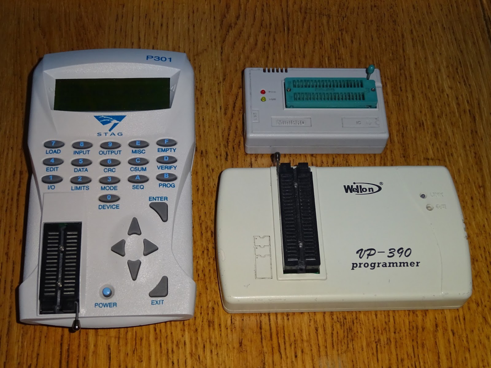
The smallest, cheapest, and easiest to use is the MiniPro TL866CS. This is the one I normally turn to. It is suitable for most modern chips up to 40 pin, and 12.5V programming voltage. It doesn't do so well with older chips which need higher programming voltages. It also has a few gaps in it's device support. For example, it can program the Lattice GALs 16V8 and 22V10, and the Atmel ATF16V8, but not the Atmel ATF22V10.
The one below that is the Wellon VP-390. This is larger, more expensive, and less easy to use. I tend to use this one only when the MiniPro can't help. It does support the ATF22V10 for example, and also chips up to 48 pin. It is also a bit flaky on older, higher programming voltage chips.
The Stag P301 is an older device, and communicates via RS232, but can be used standalone to copy chips. This does cope well with older EPROMs which need 21V even 25V programming voltages, it also supports some unusual chips such as the TMS2532, which is handy as it fits into Commodore PETs without needing an adapter like a 2732 does.
Unlike the USB programmers, this device relies on a memory buffer when programming. This can be read from another chip, or can be transmitted via RS232.
This does have the downside that it requires the device to have enough memory to hold the size of EPROM you are programming. The default device has 128K of RAM, enough for a 27C010 EPROM, but not enough for a 27C020, 040 or 080.
Stag did provide a way to upgrade this up to 1M (enough for a 27C080), using a plug in module, the P322. TFW8b had one of these. Only one of them, and that wasn't going in the programmer I was getting.
With that installed, the device is fully loaded with RAM. I put out a call out on twitter a couple of weeks ago, and located a few more of those, but none that were available.
I did think about trying to clone it, but it's quite a fiddly board with RAM chips on both sides, and small pitch connectors, so it would be a lot of effort. It may be possible to write some software to program the chip in 8 chunks, if it can offset the programming address. The current software doesn't support that, so it would mean working out the serial protocol and writing some new code.
At the end of the day, it is only necessary to support the largest chips, which tend to be modern 12.5V programming voltage devices, so both my USB programmers can handle them. It would still be nice to get one of those upgrade modules if anyone happens to have a spare P322?
The RAM expansion module hides under the battery pack. It is an interesting design. Actually no, let's be honest, it's an awful design. The battery pack is quite heavy, and isn't held that well by the plastic clip, so has a natural desire to fall out, or at least to slip out just enough to break the contact.
The battery pack is 8.4V, 650mAh, made up of 7 AA size rechargeable cells. These were originally 650mAh NiCd, but had failed in the past, and been upgraded to 2000 mAh NiMh cells. This wasn't holding charge anymore, and when I checked, four of the cells were measuring around 0.1V. I did try, but they were not willing to be recovered. The others seemed healthy, but couldn't work in series with the dead ones.
The Stag does have a built in charger, but that is designed for NiCd cells, so it's probably a simple trickle charger which will not be ideal for NiMh cells. This is likely to have led to the dead cells, if any of the cells are a bit lower capacity, they can put stress on the other cells. If one in the middle needs extra charge, that current has to pass through all the other cells, which just heats them up if they are charged.
Rather than order some more AA tagged NiMh cells, and go through the same cycle again, I looked at some alternative options. My thinking was to try to mount a battery pack inside the recess of the case, where the original battery pack fitted. I looked around, but there didn't seem to be many 8.4V packs around that would fit.
My next thought was to use some AA battery holders, and use AA eneloop cells. This would have worked, but didn't quite fit in the cutout, so it would have been resting on the cells, not ideal and they would be liable to fall out.
The next idea was to use AAA cells. Modern AAA rechargeables come in capacities greater than the original 650mAh NiCd cells, so it would be at least as good as the original, in fact about 50% better.
The AAA holders fitted nicely, and would allow me to use part of the original battery as a cover. There were some foam pads which previously held the cells in, I have left that in place, but I don't think it's actually touching the AAA cells in their holders.
I stuck the battery holders in place with foam pads. I couldn't find any 7 way holders, so I used one 4 way and one 3 way, wired in series, and slightly reluctantly soldered to the battery contacts. I was going to try some kind of clip, but thought it was more important to get a good contact.
I dug out seven AAA eneloop cells, and topped them up in the charger. The plan would be to remove them when they needed charging, and charge them individually in a decent battery charger (such as this TechoLine BL700).
With those installed, the Stag powered up and showed the batteries as fully charged. I read and programmed several chips like this, and it seemed to be working nicely.
However, after I had finished programming various test chips, I checked the battery level again, and it was down to half. As a side note, the next job is going to have to be fitting a backlight or swapping the LCD for one with a backlight.
I checked the cells, and they were showing different voltages. I put this down to the fact they had led different lives, some had been used in my old DECT phones which had unsuitable trickle chargers that tends to damage the cells over time, others may have been in lower drain applications like remote controls. These were just some spare batteries I had lying around to test out the idea of running this from a pack of AAAs.
I put them in the charger to top up. They had all been full, but after recharging, it was clear they had been unevenly worn, one cell took only 81mAh to fill it up, another needed just over 1Ah. Just goes to show that even though those cells that had come out of the same batch, they had very different lives. Always remember, never mix batteries types, ages or chemistries as they are almost guaranteed to discharge at different rates, and the two cells that went flat quickly had compromised the whole battery pack.
As a temporary solution, I fitted a set of standard alkaline batteries. It goes without saying, don't plug in the mains adapter with non-rechargeables fitted. I don't actually have one of those for the Stag, so it is unlikely. This did work fine, and it is good to know that it is an option, but I would prefer to have rechargeables if I can.
A better solution is to get a new pack of cells and fit them all at the same time, and keep them as a set so they will hopefully age equally. I ordered a set of 10 Fujitsu 950 mAh NiHm cells, and installed 7 of those instead. They have been in use for a while now, and the battery is still showing full, so I think that is a result.
The cover fits back in place, and is more likely to stay there now there is no weight pulling it open.
2025 update
See the follow on post with a further battery upgrade and a RAM upgrade: