
Over many years of repairing computer like the Commodore PET, I have designed various little boards to replace unobtainum parts, or assist with diagnostics. I get occasional requests for these, so I thought I should list them properly.

Some of those will be well known, such as the PET ROM/RAM and the SD2PET. I will put links to all of those at the end of the post.
PET 6550 Video RAM Replacement
One of these I use a lot is the 6550 Video RAM replacement. Early Commodore PETs used their own MOS ROM and RAM chips, rather than standard tried and tested parts like the 2114 SRAM and standard mask ROMs.

The design of these was an interesting idea that worked differently to the standard parts.
This section grew into a post of it's own. Read all about the MOS 6550 RAM chip here - http://blog.tynemouthsoftware.co.uk/2024/06/mos-6550-ram-chips.html
TLDR: They fail, overheat and start to damage other parts on the boards. If you have a board with 6540s and 6550s, I would strongly recommend removing them and using a PET ROM/RAM board instead.
I designed a board which can be used to replace the video RAM with a modern RAM chip, which means you can preserve any working chips you have and have a cool running stable and reliable machine.

I later revised that to use larger footprint packages that were easier to produce.

And that is the version I have been using.

And the version I have now listed on Tindie.
Assembled and tested and ready to go.

The pins fitted should be suitable for most sockets, and have worked on all the boards I have used these on. I have not needed to replace any of the sockets, and you are unlikely to find 22 pin 400 mil spacing replacement sockets, so if you need to, you would have to use socket strips or solder the board directly to the PCB.

2114 Video RAM replacement
Later PETs used 2114 video RAM. This is much more reliable, but does still occasionally fail, so I have a board that can be used to replace that. The PET video circuitry, particularly the later CRTC based machines, is very picky about RAM timings, and it can sometimes be difficult to find a set of vintage new old stock 2114 chips that work in this situation.
The board is designed to replace 2x2114 static RAM chips used as video RAM on most PET models.

This one is a straight swap. No timings or gating or select issues to address.

That works well on the 2001N machines as above, and is also be usable on 4000 and 8000 series machines. A 8032 has four 2114 chips, so you would need two of these boards.

The 4032 uses the same board with only two of the RAM chips populated.

The spacing is correct for the video RAM on these machines
It could also be useful anywhere there are pairs of 2114 chips with this spacing, although I haven't found any yet. The ZX80 and VIC 20 CR are too close together and the ZX81 is too far apart. The 2 pin VIC has the right spacing, but the pairs are vertically aligned, not side by side. So just the PETs for the moment.

These are available built and tested:
PET 6540-010 Character ROM replacement.
The character ROM on early PET 2001s is a 6540 ROM (6540-010). Later PET 2001s moved to a mask ROM (901439-08).
The PET Character ROM replacement does two jobs. Firstly, it can be used to replace a faulty 6540-010 ROM chip.

Secondly, it allows you to select between two character sets. If you use a PET ROM/RAM to upgrade to BASIC 2 or BASIC 4, this will be the correct character set. BASIC 1 is of limited use due to various bugs, but if for some reason you want to do that, you can select the original character set using jumpers under the ROM chip.

The 6540-010 was the character set for BASIC 1, the one which seems to be a more sensible arrangement. The uppercase characters remain the same in graphics or text mode and you get lowercase characters or more graphical characters in the other mode.
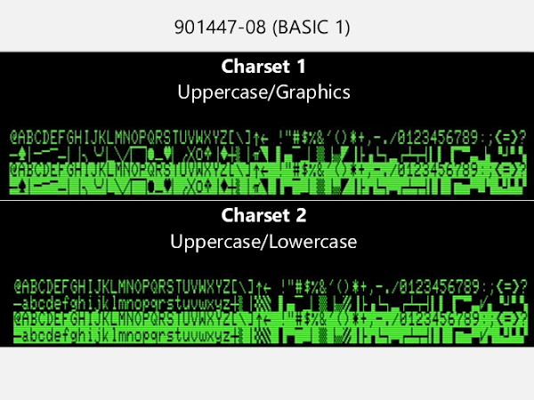
For reasons lost in the mists of time, they reversed that for BASIC 2, and kept that less logical arrangement for BASIC 4. When you move to the other character set, lower case is the norm, and the upper case is moved to where the graphics were. (this is why the 8032 etc. with business keyboards have "ready" prompts and 4032 and other graphics keyboard machines have "READY" prompts)

The board and ROM are available assembled and ready to go.

PET Video Out
I seem to have produced lots of these over the years in various shapes and sizes.

The earliest plugged into the userport and datasette port (for power). I used that for a long time on my PET 2001 test board, but it's not ideal as it blocks the userport for other things, although there is a passthrough for the datasette.

In the end I wasn't happy to sell that as it was quite a job to remove, and it might be possible to damage the edge connector if you go at an angle instead of straight backwards.

I did a version as two boards. Not sure what happened to that. I think a few of these things just came along at the wrong time.

I also had another version at the same time, and I think that is the best one to go with.
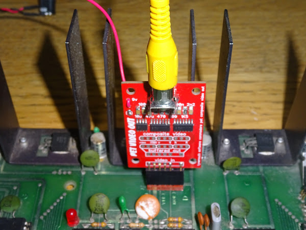
This one fits internally onto the monitor connector and gives you composite video. Well it gives you monochrome composite video in NTSC, slightly shifted to the right.
Even in PAL regions with 50Hz power, the PET video output is 60Hz. Many modern monitors support NTSC composite input.
Later CBM 40xx and 80xx models with CRTC based video circuits generate video at different frequencies, not compatible with most monitors, so this can only be used with 2001/2001N/30xx and 9" 40xx machines.
The board has a an onboard 5V regulator to avoid noise, so it need to be clipped to a 9V source, the polarity protection diode is usually an easy choice.

You then have all you need to get composite video out of a PET for bench testing.

The same diode can be used on 2001N boards, but it is a little more crowded there.

As always, available built and tested from my Tindie store

Extra credit section
It is possible to use it on a CRTC based PET, but you need a custom edit ROM, and you need to change the jumpers to cope with the different sync polarity. I left space for jumpers to change this, but they are the sort I used at one point where I pre-wired the jumper with a PCB trace, so you need to cut that if you want to fit a jumper. It seems to work in this case as most users will just ignore the pre-wired jumper section and use it as is. There are also pads for a buffered video output with selectable polarity, but again, that is advanced users only. I may do another version with all that missing and just the standard composite output.
I could supply a version with the patched editor ROM.

But there are also two positions of the monitor connector, so it would need two versions. One in the middle of the board, for the earlier 8032 boards.

And one for the Universal Dynamic 40xx/80xx board where it is right at the bottom edge.

I think I started looking at these options in the past and just bailed out of the whole project as it got too complicated and there were too many options and someone always wants yet another different option. And then someone asks if it will work on a SuperPET and I just give up and delete the listing again. One of the reasons I haven't listed these sort of boards in the past is there are so many caveats about which machines are and are not supported, and a lot of people don't bother reading those and might end up with something unsuitable for their requirements.

Advertisements

This is the full list of links for those parts, plus more that you can see in the picture above.
6550 Video RAM Replacement
2114 Video RAM Replacement
6540-101 Character ROM Replacement
PET Video Out
PET Diagnostics
PET IEEE-488 Diagnostics
PET 2001 Video Glitch Fix
PET ROM/RAM
SD2PET Power Tap
Dual 9 way D Userport Joystick
Further links can be found here:
Patreon
You can support me via Patreon, and get access to advance previews of posts like this and behind the scenes updates. These are often in more detail than I can fit in here, and some of these posts contain bits from several Patreon posts (they also got an extra post covering the history of my 6550 video RAM board). This also includes access to my Patreon only Discord server for even more regular updates.


