Showing posts with label 4080D. Show all posts

Sunday, 3 September 2023

Damaged Mini PET 40/80D Repair

This is a first. A Mini PET 40/80D that is no longer working.

I don't think TFW8b has had many support messages about the 40/80D. Most were technical enquiries about it's suitability.

  • No, it won't work with a Super PET.
  • No, you can't use it with a Commodore 64 keyboard.
  • Yes, I know The 8 Big Guy did that in a video.

This was the first user to actually have a problem.

The board had arrived, been installed in a PET 2001, powered on and worked. Power on chirp, READY prompt on the screen etc.

Great, that's what it is meant to do.

(yes, that is my PET 2001, I didn't have a photo of the user's one, call this an artists impression)

But then, when they went to turn it on a second time, it was dead. There were some LEDs lit on, but no chirp, no video?

The owner was helpful enough to try some different power supply and monitor options to see if we could narrow it down, but in the end, the best option seemed to be to send it back to me to investigate.

It arrived fairly quickly, the original packaging surviving a second trans-Atlantic flight, and the board looked fine.

No obvious physical damage, nothing to suggest anything wrong.

I powered it on from a 9V DC bench supply, and it drew about 400mA, which is high for one of these boards, they are normally around 150mA.

The LEDs near the SD socket flashed at power on as normal, so that was alright.

The power LED was on, as were the two datasette motors LEDs, but the Ready LED was off.

Normally, a few seconds after power on, the Ready LED goes on, and the motor LEDs are turned off as the PET boots up.

That wasn't happening.

Poking around looking at voltages, the 9V input was there, dropped slightly by the polarity protection diode.

The 3.3V rail was there, and the the things like the SD card LEDs were behaving normally.

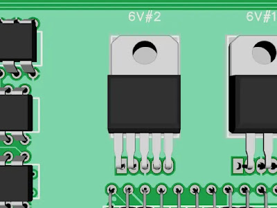
The two 6V motor supplies were enabled and at the correct voltage.

The 5V rail was reading 0.7V.

Ah, there's ya problem.
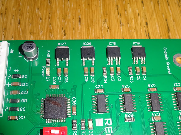
The 5V regulator (IC26) was getting warm. 

I powered off and checked for shorts, and yes, the 5V rail to ground was reading a bit over 1 ohm. So there was a short somewhere.

I checked around again for anything obvious.

I also probed around, trying to find a spot where the resistance was lower, but it all seemed to read about the same, and went down as you were reading it, presumably because of all the capacitance on the rail.

Difficult to track something like that down without being able to remove chips, and these are all surface mount.

Well, there were two EPROM chips in sockets.

I removed those.

It wasn't them.

I though I would quickly try the fingertip test to see if any of the chips were getting hot.

I didn't want to damage the 5V regulator by running with a short any longer, so I powered the 5V rail direct from the bench supply at 5V.

Current limiting again kicked in, but none of the chips were getting noticeably hot yet, so I kept winding up the current bit by bit until at about 700mA I noticed one of the chips was getting hot.

It wasn't clear at first, but once the current had been increased, it became clear that the 74HC86 was burning hot and the others were just warm due to conducted heat.

The 74HC86 is the third one down, next to C41, for those playing along at home.

I was fairly confident that was the problem, so I removed it and fitted a new 74HC86. 

It I wasn't sure, I would have removed it and checked for shorts again, but I had an idea why it might have failed, so just went for it.

I plugged it back into the power (and was confident enough to also plug in a monitor), and powered it on.

There was a chirp.

There as a ready LED.

There was a READY prompt. (one day I will get better at taking photos of screens, surely I have to some time, right?)

Success.

All down to this one pesky chip.

Self test ran for several hours, and several power cycles, with no problems, and the current as a respectable 150mA.

But why did it fail?

Well, only two gates on that chip are used (don't worry, the inputs of the other two are tied to ground). Of the two used gates, one drives the video signal into the composite video mixer amplifier, and the other drives the video signal to the PET monitor.
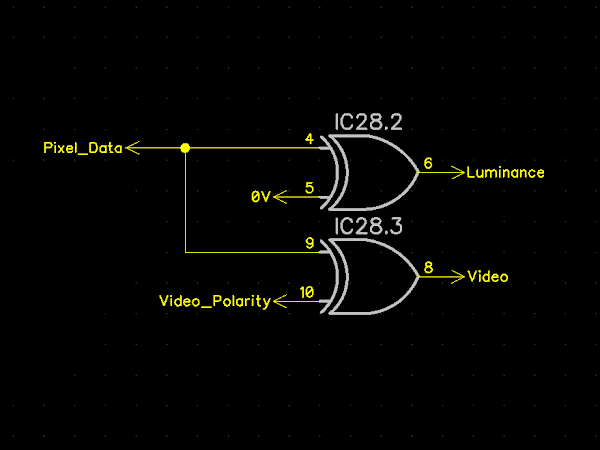
This is the same circuit as used in hundreds of Mini PETs, Mini PET 40/80s and Mini PET 40/80Ds, and there have been no 74HC86 failures as far as I know with any of those.

It is also essentially the same output stage as the original PET, although that had an extra pull up resistor added as the 74xx series could only really drive low, so that boosts the internal pull up on the high side.

My theory is that there must have been some high voltage pulse on the video line from the monitor that fried the 74HC86 chip on the 40/80D.

The PET monitors are pretty basic, so it is possible that some fault in the monitor is causing high voltage on that line. When I say high voltage, I mean "anything above 5V". There are 12V, 85V and 400V rails in there, any of which could kill a poor little logic chip.

The obvious one is in the input stage, this is a slightly odd level shifter.

When the video input is high, CR1 is reverse biased, so there is no current flow through it. 12V goes via R1 through two diodes CR2 and CR3 and the transistor base emitter junction, which is effectively another diode. That should mean the point at the bottom of R1 should be at about around 1.8V, and Q1 will be conducting, and further down the line, an electron bean will strike some phosphor and a pixel will glow green (or white depending on the phosphor).

When the video input is low, CR1 conducts, and brings the end of R1 down to about 0.6V. This will turn Q1 off, and also stop the flow of electrons, and the pixel will be black.

If CR1 has failed short, or is leaking, it could let the 12V down the line to the video connector and to the 74HC86, and even via a resistor, could damage it. (I don't have the users monitor here to verify or repair this, it is just a theory)

The design is much the same with the 12" PET monitor, other than the polarity is reversed somewhere along the line, and the input voltage is now 18V (marked as E18 for some reason best known to whomever drew the schematic).

So that's my guess what happened. A short or leaky CR1/D201 fried the 74HC86. I wouldn't be surprised if the same fault fried the 7486 on the PET motherboard that originally drove that monitor.

The repaired board is ready to go back, but I am worried the same fault could fry the new chip as well.

I am wondering about adding a pair of clamping diodes on that pin, to protect the chip.

There was never anything like that on the PET video connectors, but maybe a good idea in this case.

Commodore added that arrangement of diodes to later C64 and early plus/4 boards, a factory fitted mod to protect the inputs on the IEC port (presumably after all the 7406's started dying). They were also added to the C64C and later versions of the plus/4 schematic (but not the Commodore 16).

I added clamping diodes to all three signals on the video connector (the other three pins are ground). The two sync signals come from the microcontroller, and should already have internal protection with a similar arrangement of diodes, but this is just extra protection.

And just to reiterate, I don't think anyone else needs to fit these, it is only this particular case of a faulty monitor.

It is always tricky with this sort of "here is a one in a million weird fault you will probably never see again" fault. They inevitably lead to people saying "I replaced the chips you said, but it didn't fix it".  

Fix what? did you have that same one in a million fault? "no mine was different, but I thought I would fix it......"


Advertisements

Mini PET 40/80D

There are one or two Mini PET 40/80D boards still available from The Future Was 8 bit:

More info in a previous post:

http://blog.tynemouthsoftware.co.uk/2022/03/the-mini-pet-4080d.html

Mini PETs

The original 40 column Mini PETs are available from my SellMyRetro store in both B (internal green boards) and A (stand alone white boards) versions.

Mini PET B

The B version is designed as a drop in replacement for the PET mainboard.

This is available in built and tested, full kit and partial kit form:

Mini PET A

The Mini PET V1.48A is a standalone version, also available in built and tested, and partial kit form (let me know if there is interest in a full Mini PET with keyboard kit):

As well as a choice of matching keyboards PCBs.

Patreon

You can support me via Patreon, and get access to advance previews of posts like this and behind the scenes updates. These are often in more detail than I can fit in here. This also includes access to my Patreon only Discord server for even more regular updates.

https://www.patreon.com/tynemouthsoftware

Sunday, 19 June 2022

Powering Commodore Datasette Drives

After last weeks post covering the modification of a Commodore datasette drive to create cassette masters, literally no one asked for more details on how the datasette drive was powered. So I thought that was a perfect excuse to go into considerably more detail on the subject.


The datasette was first introduced to go with the Commodore PET in 1977, and remained in use right through into the early 1990s. The original PET was almost entirely 5V. All the logic, ROM and RAM was 5V only. These were the days before the 4116 DRAM chips which need -5V and +12V as well. 

The exception to the 5V only statement is the datasette drive. It has a 5V supply for the internal logic, but there is a separate power connection for the motor, which should be supplied with 6V.

The arrangement is different from most cassette mechanisms. Normally there would be a permanent 6V supply for the motor, and a mechanical switch on the drive itself to turn the motor on or off, sometimes in series with a relay controlled switch on the computer end. The Commodore datasette relies on the host to use the sense line to detect when a key is pressed on the mechanism to turn the motor on or off. 

You will see some situations where these are driven from 5V, for example the old parallel port X1531 type transfer cables. These run the motor slowly, 5/6 of normal speed. This makes the tape move more slowly, so the data is written closer together on the tape. When played back at normal speed, it will actually be 20% fast. This is just about within the tolerance of the loading routine, so can speed up loading a bit, but it's not guaranteed, and wouldn't be recommended these days.

PET 2001

The PET's power supply was 9V DC unregulated, with several 7805 5V regulators, so 9V was available, and that was used to generate 6V for the motor.

There is quite a lot going on there. If you ignore the resistors and 2N3904 on the left, what you have is a 7.2V zener diode fed via a 1.5KΩ resistor, which gives a regulated 7.2V reference. The 10nF capacitor smooths the reference voltage, which is then buffered by the two transistors in a darlington arrangement. The output is a regulated supply of 7.2V, minus the two base voltage drops, 0.6V each, giving a 6V supply. 

Bringing back the 2N3904, when the Control signal is low, the 2N3904 is off, and does nothing, and the output voltage remains at 6V. When the control signal is high, the transistor is turned on and pulls the 7.2V reference voltage down, and in turn, the output transistors are turned off and there is no output.

That gives a simple switched 6V output. Control is high, motor is off. Control is low, motor is on.

VIC20 / C64 / C128 / TED

Over the years, that circuit was revised a few times, and I found quite a bit of variation from model to model and machine to machine. Different drive transistors, different zeners etc. The voltage is always "around 6V", but it varies from a little over 5V to almost 7V on some of the machines I have tested.

The final version in the TED machines like the C16 and plus/4 was much simplified.

This used a 7406 gate to replace the 2N3904 transistor, but still doing the same job of pulling down the reference voltage when the drive is not in use. Gone is the second buffer transistor, so more current is drawn from the zener reference, which had it's resistor value dropped to 470Ω. That does mean that when the motor is off, the 470Ω resistor is across the supply rails and wasting 20mA all the time.

Mini PET

When I designed the original Mini PET, I used the design from the TED machines shown above.


The two datasette drive circuits were drawing 40mA in total, with the rest of the board drawing less than 100mA, but it was nice and simple and a product of the last generation of Commodore optimisation. 

Mini PET 40/80

When it came to the Mini PET 40/80, there was an additional challenge to deal with, soft power on/off. I could have stuck with the same circuit, but the 40mA draw would have been present when the rest of the unit was switched off, not ideal. I could have added a separate transistor, probably a MOSFET, to switch the 9V rail before this circuit, but I was trying to simplify things.

I had used some new surface mount 6V regulators with on/off controls in the multi port duplicators I had made for TFW8b. Each drive had it's own switched and regulated supply, which worked quite nicely. I was able to use the sense input directly to switch them on or off, so no additional logic was required, not even a pullup resistor.


I would have like to use those, but they were only available in surface mount, or the sort of 5 pin TO220 packages that might be a problem for some kit builders as the leads are a bit close together. 


After looking around for quite a while for alternatives, I finally settled on the Micrel MIC2951. (Micrel is now owned by Microchip, but I haven't seen any Microchip branded as yet.)

This little 8 pin chips work in two modes. In the first mode, they are fixed 5V, 150mA regulators, with a shutdown input so they can be turned on or off via the soft power on controls.


The Mini PET uses less than 100mA, so 150mA should be fine. I used a second 5V regulator to supply the datasette port, more than enough for a datasette drive logic and powering an SD2PET.

The second mode allows the voltage to be set via a resistor divider (like an LM317 if you remember those). The shutdown signal is the same logic as the datasette control, low is on, high is off. A 74LS07 gate is used to pull the signal low when the motor should be on, the rest of the time, the 10KΩ resistor pulls it high and keeps the output turned off.


The value is set using the following equation, Vref is an internal 1.235V reference, and R2 is using the recommended value of 100KΩ. The nearest standard resistor value to give the output voltage we need is 390KΩ.

That gives an output voltage of around 6.05V. The value depends on the resistors which have a 5% tolerance (absolute worst case 5.59V-6.56V). The exact value is not important, as long as the voltage is within range and is constant during playback. Speed was expect to vary over the life of the drive due to belt stretching, so is accounted for in software (by timing the header tone at the start). The output is current limited to 150mA, to avoid motor burnout when rewinding or fast forward is left pressed and the end of the tape is reached.

That left the power section of the Mini PET 40/80 as four identical MIC2951 chips, and a pile of passive components.

Mini PET 40/80D

When it came to the Mini PET 40/80D, I was able to go for one of the surface mount 6V regulators with enable pins, so no need for the resistors, these were pre-set for 6V. The 5V regulator next to them is a plain fixed voltage always on type, as there was no need for soft power on with the 40/80D.

The on/off pin was now the inverse logic, so I needed to use 74LS06 dates to drive those, but it at least there were no zeners or set resistors.


Advertisements

The Mini PET 40/80D is still available from TFW8b (whilst stocks last)

https://www.thefuturewas8bit.com/shop/tynemouth-products/minipet4080d.html


This post is an combination of several posts from my Patreon. If you want advance previews of posts like this and behind the scenes progress on new projects, you can follow along and support me on Patreon (which now includes access to my new Discord server)

https://www.patreon.com/tynemouthsoftware


Sunday, 15 May 2022

PET Sounds

In recent months, between the new posts, I have been posting update versions of content previously published on my Patreon. This one is slightly different as I have effectively recreated the Patreon post using some new kit. More info on that later, but I will hand you over to past me writing on Patreon.....

I have been writing a few games for the Commodore PET / Mini PET recently, and I wanted to add sound to them.

Later models of PET have a 1 bit sound output, A piezo transducer which can be set as on or off. To create sounds, you turn it on and off quickly. 

And that's the end of today's post. Goodbye.

...

OK, so maybe you want some more detail. I couldn't find much information on how exactly to achieve the "turn it on and off quickly" bit, so I thought I would document what I worked out.

Back in the days of the first PETs (to be precise, all the 9" non-CRTC PETs), the PET didn't have any built-in sound capability. Games like Space Invaders benefited greatly from sound, so the PET implementation contained instructions on how to wire up a speaker to your PET so that when you hit an alien you heard the noise.

The idea is basically taking the output from the CB2 pin on the user port and feeding it to an audio amplifier. This concept was taken onboard by Commodore when they produced the 12" CRTC Based CBM machines (which we all still call PETs anyway - see a future post for the long and detailed story behind that).

Here they took the CB2 output but also ANDed it with the DIAG pin on the user port, PA7 on the keyboard PIA. This is the pin that should be pulled low to activate the machine code monitor on boot. Not quite sure why they did that, it means you can drive the speaker from two different outputs, so I suppose you could technically have two voices or create some kind of tremelo effect?

For the Mini PET, I wired up a piezo transducer to the same signals.

Whilst the diag pin is an option, I will concentrate on the CB2 pin, as this will also work on any PETs adapted as per the Space Invaders instructions. (and also with the piezo on my PET dual userport joystick board - see the end of the post for more info)

Method one - bit bashing

One way to make sounds is to turn the CB2 pin on and off quickly. CB2 is designed for handshaking, so it needs to be driven differently to a normal IO PIN.

The VIA PCR (Peripheral Control Register) is at address $E84C (59468). This controls 4 pins, CA1, CA2, CB1 and CB2.

CA1 and CB1 are input only, and can't even be read directly, all they can do is trigger an interrupt. CA2 is used to control the video character set, low is uppercase / graphics, high is lowercase / uppercase. Any changes made to that register need to keep these other settings intact.

The values for normal operation are $CC (204) for off, $EC (236) for on. The first thing to try is a simple BASIC program.

However, that's not particularly fast, and the output is switching at just under 50Hz. Congratulations you have created a mains hum simulator. Take the rest of the day off.

Here it is interesting to look at some of the speed improvements you can get by optimising the simple BASIC program.

I thought putting everything on a single line might make any difference, but it didn't, so lets try a few more tricks. Here I am using abbreviated commands (which doesn't actually make a difference)  and assigning a variable to the address being POKEd at.

That's more like it. 100Hz, double what we previously achieved.

I next tried using variables for the two POKEd values as well.

Again another doubling in speed, now 200Hz.

That is still only 200Hz, a low, annoying hum. To create something more tuneful, we need to look to assembly language. I've been doing a lot of 6502 coding recently, so I just typed this in, but it probably needs more explanation. (ignore the BASIC programs at the start, it is the bit after the SYS4 which launches the machine code monitor)

This is a listing of the same code (looks like I got it right)

I picked $1000 as the base address as that is normally free, but the code could have been based anywhere. This does the same thing as the BASIC program, POKE one value, POKE the other value, go back to the start. Only in assembler, it does it a whole lot faster.

This is now 66.7KHz, well outside of my hearing range. To make it audible, all it needs is a delay between the on and off pulses.

Using the simplest delay loops counting to 256 gets that down to around 400Hz, so you can see it's just a case of fine tuning the delay values to get around the tone you want.

There are a few problems with this. Firstly, it ties up the processor in loops and also, you might just be able to make out some of the gaps are slightly longer than the others. This is more obvious on the higher frequency version without the delay. These are caused by the system timer interrupts, and you can actually change the tone of the sound by pressing keys (which extends the interrupt slightly).

Zooming in on the gap, the interrupt routine lasts around 640uS, during which time, there is no sound output. So this approach is not really viable in practice.

Method Two - Shift Register

Using the CB2 pin for sound wasn't just an arbitrary choice of an available I/O pin. The other thing the CB2 pin has going for it is that it can be configured as a shift register output, which will shift out at a speed determined by a counter running directly from the system clock. This has the advantage that it doesn't tie up the processor, and is not disrupted by interrupts.

This is controlled by three registers, the first of which is the ACR (Auxiliary Control Register) at $E84B (59467).

The option we want here is "shift out free running at T2 rate". So the ACR is set to $10.

The second register is the shift register value, at $E84A (59466). This controls what bits get sent to the port. The three most useful values here are:

  • $0F - 00001111
  • $33 - 00110011
  • $55 - 01010101

You can also use the inverse of those ($F0, $CC or $AA). Other values (such as $01, $03 etc. will alter the mark space ratio of the output pulse and produce a less pure note (which may be what you want).

If you think about it as they are drawing the output waveform, so the output is high when there are 1s, and low with 0s. So, the way they are shifted out, $33 will look the same as $0F if shifted out twice as fast.

The final register is the lower byte of timer T2 in the VIA chip. This controls how long it is before the next bit is shifted out. The high the value, the lower the note. 

This note will continue to play as you get on with other things, so it can all be controlled from BASIC. The final POKE 59467,0 turns off the shift register output. I am telling you that now before you have to fumble for the reset button or power switch to make the whining noise stop.

As an example, $EE will cause bits to be shifted out so that 8 bits takes 3.84mS. With the $0F pattern in the shift register, that forms 4 lows and 4 highs, which creates a square wave of 260Hz, which is almost the 261 Hz of middle C.

If I try to mark out the byte that is being shifted out, you can see the 00001111 of $0F.

If I leave everything else the same, but change the shift register to output $33 instead of $0F, the frequency is doubled to 520Hz (C5).

And again, changing it to $55, we get C6.

So that is that's all there is to it. The counter value sets the note, and the shift register pattern sets the octave. (or rather, the lowest octave - you can get three octaves from each setting with different counter values)

So what was all this for?

Well, I have been working on an adaptation of David Stephenson's Tut-Tut. That was originally written for the ZX Spectrum (as a type in listing in Paleotronic magazine - https://paleotronic.com/2019/11/05/tut-tut-a-new-game-for-the-zx-spectrum/), and then for ZX81 (https://www.zx81keyboardadventure.com/2019/10/zx81-game-tut-tut.html) and then an improved ZX Spectrum version (https://www.zx81keyboardadventure.com/2020/04/zx-spectrum-game-tut-tut-2020-ed.html) and finally a port for the Jupiter Ace / Minstrel 4th (https://www.zx81keyboardadventure.com/2020/05/tut-tut-on-jupiter-ace-part-1.html).

This is a great game, reminds me of my old favourite Repton.

The ZX Spectrum versions had a little tune (almost, but not quite, entirely unlike "Walk like an Egyptian"). In the Spectrum version, this was done as a series of BEEP commands, with a parameter selecting the full or brief version:

if ubFull then
        beep .25,-2 : beep .125,8 : beep .125,5 : beep .25,5 : beep .25,-2 : beep .25,5
end if
beep .25,-2 : beep  .125,3 : beep .125,3 : beep .25,8 : beep .125,-2 : beep .125,-2

Beep takes two values, a duration in seconds, and a note with middle C being 0.

  •  -2 = A#
  •   0 = C4
  •   3 = D#4
  •   5 = F4
  •   8 = G#4

I have described the mechanism to play the notes on the PET, now I just needed to set the duration. That wasn't too critical, so I just used a simple counter.

I added a 5mS gap between notes as that was what the Spectrum was producing.

And there was the finished song, and it sounds just like the Spectrum. Side note, I had to cheat as I couldn't quite get the A#3 note, but it's closer to that than B3.

But Dave, you said a couple of games?

Yes, well, I did try to add sound to my remake of 3D Monster Maze from the ZX81.

I tried to do the sound of footsteps and also tried a sort of Jaws type sting, but both ended up quite low notes, and sounded comically awful on the tinny piezo speaker in a PET, so it remains true to the original, silent. All you can here are the tormented screams of the player.

PET Synth

If you just want to play "music", or makes some noise, have a look at PET Synth.

The website has gone, but here is an archived link:

See also this video by Sam at Look Mum, No Computer, who built a Mini PET kit and then had a go at circuit bending it. See also most of the other videos on the channel if you like unusual ways of making electronic music.

2026 Update:

The author of PETSynth has announced PETSynth II MIDI, more info here:

Advertisements

A big thank you to Keysight who have generously donated the oscilloscope I used to get the screenshots in this post.

I am still learning how to get the most out of it, but so far it is doing an excellent job. Expect to see a lot more screenshots in future posts as these are so much better than my previous attempts to take photos of my 30 year old CRT scope.

(N.B. yes there is a plastic keycap stuck over the speaker with a bit of blu tak. Most of the tones I was producing today were not the most pleasant to listen to.)

PET Piezo and Dual Userport Joystick

If you have an earlier PET without the internal sounder, I have a board which plugs into the userport which includes one, and also two 9 way D joystick ports.

Mini PET

The Mini PET 40/80 kits to build a PET like the one I used in this article have now all sold out, but there are still some Mini PET 40/80 drop in replacement PET boards available from my Tindie store:

You can see an earlier version of that board and these games being played on this video by The 8 bit Guy

Tapes

Tut-Tut and 3D Monster Maze are available on cassette from The Future Was 8 bit:

Or digital downloads from my itch.io store

Patreon

The original version of this posts and many other advance previews and behind the scenes progress on new projects, can be found on my Patreon. I am very grateful for the support I have received from my Patreons over the last few years. If you would like to support me, here is the link:

Footnote

I know very little about music, so I may have all got the terms wrong, please forgive me.