Showing posts with label 4032. Show all posts

Sunday, 19 July 2020

Mini PET Update

This is an old post, preserved for reference.
The products and services mentioned within are no longer available.

The Mini PET seems to have been received well. I am seeing lots of pictures of very neatly assembled boards (and also the one that TFW8b built) and revived PETs up and running again.
That's great to see, and very few problems building them, other than a few people who had to built it without reference to the manual (the person packing the orders has of course been fired). So far, the only issue to report is a slight error that seems to have slipped though all of our other testers (who have, of course, all now been fired).
When first putting together the design for the prototypes of the Mini PET, I came to the userport and was pleased to find I had already drawn a component for the PET userport. Perfect I thought and added it to the design. I didn't consider at the time that I had drawn that component for things which plug into the userport on a PET, not for the host side of the PET userport, which is the mirror of that pinout. (I have, of course, also been fired)
And so, the pinout is reversed. Pins that should be 1,2,3,4... are 12,11,10,9... During testing, no one it seems noticed that, as no one it seems has anything that would plug into the PET userport. The only things I had were userport sounders and composite video output. All of which were already provided on the Mini PET. I think this will only affect a handful of people making userport serial interfaces, as the PET seems to have hardly any commercial userport peripherals.
I have made some boards which reverse the pinout. An interesting routing problem, 12 wires what all need to cross over each other and the same on the other side of the board.
I'm fairly happy with the solution I came up with, although I wonder if there is a neater way to reverse the connections? Those are being sent out to anyone with an affected board (V1.42, V1.44), although no one has actually asked for one, and only one user has reported a problem. The ones going out have white soldermask.
I build a little LED tester plug to make sure that was working correctly.
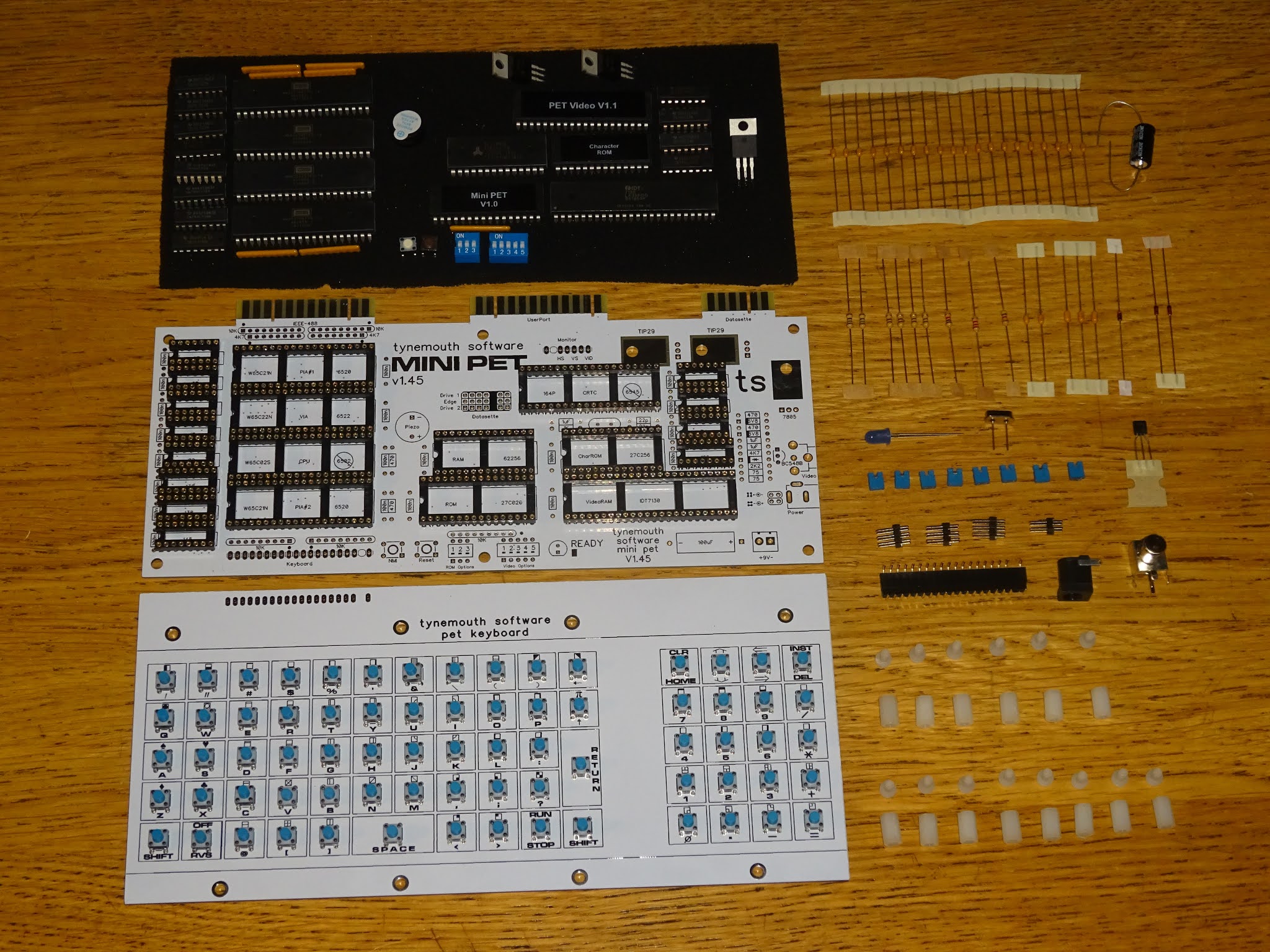
Because of the userport problem, I have moved more quickly than planned to the next board designs, as correcting the pinout on the userport required quite a bit of rerouting. The updated versions of the 'Kit A' boards is V1.45.
Other than the correction to the userport pinout, and a couple of minor tweaks, this is pretty much the same as before.
The LED tester confirms the pinout on these boards is now correct, so the twister boards are not required for V1.45 and later boards. The new 'kit A' versions (for use stand alone with a keyboard) are shipping now.
The Mini PET boards had been designed to be the same size as the keyboard PCB, which had already been designed as a direct replacement for the chiclet keyboard on the 2001 PET, so the Mini PET was designed to be the same width as that.
That meant it wasn't quite wide enough to pick up on the two mounting pillars at the back of the PET case.
I had tried out a green soldermask version of the Mini PET board and that had looked better inside the PET case. It seemed a good opportunity to split this into two versions, one white soldermask board, the same size as the keyboard, for stand alone use, Kit A. The second, a green soldermask board which fits inside the PET, kit B.
The first thing to do was to make the B boards larger, so they are now the same width as the top end of the original PET boards.
So those now fit into the case and pick up on both rear mounting pillars.
It also seems a good idea to remove things not required for this version.
I've removed the DC jack, and boxed off the composite video section, which can be fitted if you need it, but otherwise can be left unpopulated.
You can see here I prefer to fit the smaller logic chips without sockets. They are still supplied in the kits if you want to use them, I just think it looks better without. TI uses the same moulding for 14 and 16 pin chips, so when aligned correctly, you don't see the difference between 14 pin and 16 pin chips.
The wider kit B boards now pick up on both rear mounting pillars, and the power supply interface board has been integrated to make a single board solution.
As before, this can be used with the 9 way power connector found in most PETs or the 5 way connector from the original 2001s. You could cut down the pin header before soldering if you are only going to be using the 5 pin connector. But it's not a problem if you don't, one missing pin is an extra ground, the other two are for a second transformer winding which is not used.  
There is now a side datasette port, for datasette 2, positioned as on later PETs, so the board gives access to both rear and side datasette ports.
This now works better for the 8032-SK case where the board is mounted at 90 degrees, and the side port becomes the rear port.
The board picks up on the same two mounting points and the extension cables connect as normal inside the 8032-SK case.
The board can alternatively be mounted further into the PET case, which allows an SD2PET to be installed inside the case. This can be useful in unattended events to keep it away from prying hands, or for those short of desk space, or wanting to access the SD card by lifting the case rather than reaching around the back.
The second datasette is still accessible through the holes in the case in this configuration.
You will see I have moved over to using jumper settings, rather than DIP switches on the B boards (thinking it would be adjusted less frequently once mounted inside a PET case). 
I'm not sure about this, and may go to a single 8 way DIP switch on future boards as it adds quite a few extra parts to be sorted out and soldered in, but keep the onboard labelling of options.
These kits are being distributed by The Future Was 8 bit. My Tindie store remains closed due to the ongoing problems with shipping. 

2022 Update: The Mini PET has been replaced by the Mini PET 40/80. This has a built in much nicer keyboard and supports 40 and 80 column mode. Also available is the Mini PET 40/80D, a preassembled drop in replacement board with a built in SD2PET. Both are available now from The Future Was 8 bit.

Sunday, 27 August 2017

Commodore PET video RAM faults

This is an old post, preserved for reference.
The products and services mentioned within are no longer available.

This seems to be quite a common fault throughout the range of Commodore PET machines, so I thought I would roll up several repairs into a single post.
On power on, you get a screen full of characters, and there is something that looks about right, but all the letters look wrong.
If you look closer, you can see that in this case, the numbers and some of the letters are right. This is what it should say.
Now we need to do a bit of maths. First you need a table of the PETSCII character set (which is not quite the same as the ASCII one). This screen is generated by my PET Diagnostics board, and is quite handy for this.
Look up the values of some of the characters which are displaying correctly and incorrectly and look for a common factor.

Expected
Hex
Binary
Displayed
Hex
Binary
R
12
0001 0011
R
12
0001 0011
E
05
0000 0101
U
15
0001 0101
A
01
0000 0001
Q
11
0001 0001
D
04
0000 0100
T
14
0001 0100
Y
19
0001 1001
Y
19
0001 1001
3
33
0011 0011
3
33
0011 0011
*
2A
0010 1010
:
3A
0011 1010

From that it can be seen that the characters all being displayed all have bit 4 set, even the ones that shouldn't have bit 4 set. So the RAM chip which stores bit 4 is faulty (or sometimes the buffer that writes into it, or the latch which reads out of it).
On earlier 40 column machines (usually the ones with 9" monitors), there are two 2114 RAM chips. One handles bits 0,1,2 and 3, and the other bits 4,5,6 and 7.
Later CRTC based 40 column machines, there are two 2114 chips next to the empty spaces where the 80 column circuitry would go.
On 80 column machines, all four RAM chips are populated. Each pair handling alternate characters, so if you have the same bit 4 fault on an 80 column machine you would see alternating faulty characters.
You can see the first, third, fifth etc. characters are all correct, and the second, forth, sixth etc. have bit 4 stuck high as above.
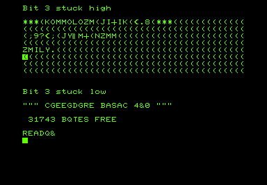
I have written a program to simulate bit faults in the video RAM:
You can also see whole RAM chips failing, so you all four bits in the upper or lower nibble are stuck.
Finally, if both RAM chips are faulty, you get a nice chequer board pattern or a screen full of @'s.
The 2114 RAM chips used on most PETs are still available, but the 6550 RAM chips used in some of the earliest 2001-8 models are more difficult to locate. You can just see them under the dust.
This 2001 appears to have one dead chip, you can see the same O's and /'s pattern in the simulations above.
Swapping the chips around shows the opposite problem, so it is definitely a faulty chip.
I have built a module which can plug in and replace both of those chips.
I haven't listed these for sale, but if anyone needs one, let me know.
In this case, once the display was working, the RAM count was short, one of the main bank of RAM was faulty.
The spare working video RAM chip was used and the full 8K restored.
It is worth noting that a common fault on the 6550 RAM chip is the enable lines, there are several of them and the seem to fail in a way that enables the chip all the time, drowning out or fighting with whichever other chips should be active at the time.
When used as video RAM, the enables are not required, so you can sometimes shuffle the chips around so the ones with faulty enable lines are used as video RAM. I didn't have any spare dust to reapply to these chips.
Here is the same sort of fault, this time on a TRS80 Model I. Unusually, it only affects part of one line, which is showing '£' characters.
The characters all work when typed anywhere else on the screen, just the £ sign appearing on the end of that line.
Typing into that area shows characters are being modified, and the space is being shown as a £, in the same way as the space on the PET was shown as @ or / etc. depending on the fault.

Expected
Hex
Binary
Displayed
Hex
Binary
q
31
0011 0001
1
71
0111 0001
r
32
0011 0010
2
72
0111 0010
space
20
0010 0000
£
60
0110 0000
*
2A
0010 1010
j
6A
0110 1010

These all point to bit 6, which on the TRS80 is a bit unusual as the video RAM is made up of 7 chips with bit 6 unused. Later an eighth chip for bit 6 was bodged on with a piggy back chip.
With that replaced, the TRS80 was back to normal.
Whilst on the subject of video faults, I may as well mention another few oddities. This PET showed only a flashing white cursor, which moved around as you types, but no characters.
This was down to a dead character ROM.
The character ROM is also to blame if you get characters that aren't quite right, such as the extra bar on the E here.
On most PETs, a 27C16 or 2816 can be used, but for 2001-8's with 6540 ROM chips, I have an adapter.
With that, the video RAM replacement and a ROM/RAM board, you can get rid of all the 6540 and 6550 chips and have a 2001 PET which should be considerably more reliable (and less than half the power consumption).
A permanently inverted picture can be caused by a few things, it bit 7 fault can do that, but in this case it turned out to be a 74LS74 flip flop.
The same machine also developed a screen which was full of stripes, even with the character ROM removed, so that was narrowed down to the 74LS165.
Both replaced and the machine is back to normal.
I think that's about all I can say about video faults on the Commodore PET. Congratulations if you got this far, by the way.