This is an old post, preserved for reference.
The products and services mentioned within are no longer available.
This is the story of the SD2PET future. Are you sitting comfortably? Then I'll begin.
The
SD2PET future is a new disk drive replacement for the Commodore PET and CBM range of computers, and it is available to buy now. It is not, however, the product we planned to build.
Way back in the distant mists of time (well, 2014), I repaired a
Commodore PET 4032 computer and started looking around for SD card storage options as I didn't have much software on tape. I couldn't find any available to buy, I did find one that had been sold for a while, but it seemed was no longer in production, and the creator wasn't responding to messages. I ended up making a version of that using an Arduino as a base, and whilst it worked, its functionality was limited to load and save PRG files, it didn't support disk images or any of the BASIC 4 disk commands etc.
I was then pointed towards another project that was still going, but it was at the other end of the scale, a bit overkill for what I needed, with options for a realtime clock and network interface and a big LCD display etc. In consultation with the creator of that project, I built a cut down version, the PET microSD. I kept all the pinouts the same, so it could use the same firmware as the larger device.
This worked very nicely and did exactly what I needed. When I wrote this up on the blog, there was a lot of interest, and I sold out of the first batch of PCBs I had ordered.
Given the success of those, I got in some more PCBs and took the opportunity to redesign the board to offer some different options for mounting the drives. They also went blue at this point.

2016, I'd been making these for a couple of years, usually in small batches to keep up with orders. Then one day I built a batch of boards and quite a few of them didn't work. With a little rework, I got a few more of them working, but there were still too many that appeared fine, but didn't work. This continued with the next batch, even more that didn't work. It wasn't clear what the issues was, my soldering and surface mount assembly skills were acceptable, no obvious problems there. I had no issues like this with any of the other things I was making at the time, most were pretty near 100% yield. These were less than 75%. Had I got a batch of bad, fake, or mislabelled parts somewhere along the line? was there something up with the firmware? I did find older versions worked better than the ones that were current at the time, but I never did get to the bottom of the issue.

I was busy on some other things at the time, so sold the last of the working ones and marked them as out of stock. The requests kept coming in asking when they would be available again (and did I have just one left that they could buy?). I was advised to simply drop the product, as it just wasn't working, but I decided I couldn't let people down, so I said I would do one more batch, and setup pre-orders for a month or so in early 2017. To rule out any problems with the previous PCBs, I relaid out new versions of the PCBs, with wider spacing, and to ease the manufacturing process, the original double sided board was slightly enlarged and made single sided. I ordered lots of boards, and a complete set of new parts from a different supplier to build more than enough for the pre-orders and to leave some for stock.

Despite everything, the yield this time was even worse, more than half the boards were not working. Many now exhibiting an issue where they would give an error the first time they were accessed, and then work fine after that. In brief, it would start up fine, and would start to respond to the first request from the PET, but part way through the communication, it would stop responding. Trying again immediately and it would always start working correctly, and would keep working until a power cycle. But would always fail the first access after power on. I tried all sorts, swapping parts between good and bad boards trying to narrow it down. In the end, I had to order even more parts to build another batch of boards to complete the last of the preorders. After all that work, I had ended up making a loss on the whole thing due to the number of bad boards and so that was it, the PET microSD was dead. I have since heard that the person selling the larger version was having similar issues and an equally poor yield.

I decided the best option was to start again, design my own PET disk drive, write my own firmware. There were various options for code to access the SD card, and I could learn the D64 image mounting etc. from SD2IEC. I kept going back to that design, as the Future Was 8 bit version had been refined over time, and had proven very reliable in service, with very good yield, few returns and lots of happy customers. Based on that, I tried to use many of the same parts as the SD2IEC in the new design, and also in the name, the SD2PET was born. The IEEE-488 interface hardware and software I would start again from scratch, and go back to the protocol specifications, and design afresh, trying to simplify things where possible. The amount of time that I spent starting at diagrams like these.

Since I had handed over production of the VIC20 Penultimate Cartridge to The Future Was 8 bit, and they were doing a splendid job of making those, it seemed the way to go was to see if they wanted to make the PET disk drive. For that to happen, it had to be good. It had to be reliable, it had to work every time, it had to work as soon as the customer took it out of the bag and plugged it in. Nice and simple, no need to read through lots of instructions. It also had to look nice and be unnecessarily small and so on. The original PET microSD designs of bare PCBs plugged into the back of the PET weren't really in the TFW8b style, it would need to be in a nice moulded case for appearance, and also for protection. At the time we looked at a few options, but didn't think we would have a suitable case for a drive that would plug directly into the PET, and it would be difficult to justify the tooling costs of making one specially for the PET.

After a while I came up with the idea of using the SD2IEC case. This is the disk drive replacement for the C64 / VIC20 etc. That would solve the presentation issues, it just needed a way of doing the cable at the PET end. There we hit a slight snag as when we couldn't source any suitable cable to connect to the IEEE-488 port. There are 24 pins, 8 data, 8 control lines and 8 grounds. and we couldn't get any cable thin enough to fit with the SD2IEC case.
Another delay, more thought, and then I came up with splitting the design into an IEEE-488 interface that would plug into the PET and an SD card reader in the SD2IEC case. With a limited number of connections needed between the microcontrollers in the two parts, we could use the same cabling as the SD2IEC. That looked like a winner, so we put that up as 'coming soon', and I got on with the design work again.
More delays at this point due to other projects, and the SD2PET wasn't working out as easily as hoped. The PET does some interesting things with the IEEE-488 standard, a particular example that took far to long to deal with was the DIRECTORY command which keeps stopping and starting reading one or two bytes at a time and then switching the bus around and calling a halt, then starting again.
The project has progressed to the point where we are choosing case colours. I was still working on the firmware, and also on various other projects. I don't think we've talked about this before, but your reward for reading this far is to hear about one of many products that don't quite make it to production for one reason or another. Usually that they are simply not good enough to put the names of Tynemouth Software or The Future Was 8 bit to them.
This was SD2ELK, a disk drive replacement for the Acorn Electron. The idea basically to give the Electron a ROM slot and a user port and then use one of the BEEB MMC type devices that normally plug into the BBC. The plan here was to reuse the case from the DivMMC future, and to that end, some white versions were commissioned to fit better with the Electron.

This hit the snag that most of the Electron software wasn't designed to run from disk, and expected PAGE to be set to E00, but the disk controller needs to use some of this RAM, so sets PAGE to 1200 or higher, so not many things worked out of the box. We didn't think that was going to be good enough, we didn't want people going through a whole load of programs and none of them working. There were a few options to investigate to get around this, but essentially, it wasn't the right solution. (we note that since then someone has done pretty much the same thing, and unfortunately has the same issues with the disk controller PAGE offset).

At around the same time, we got in the quotes for the tooling required to make the new connector for the SD2PET that houses the small circuit board for the IEEE-488 interface. That was working out a bit expensive than expected, so the price of the SD2PET as it was then, was going to work out a little on the high side. I remember a phone call with TFW8b discussing the end of the SD2ELK project and 'what are we going to do with all these white div cases' and the cost implications of the 'soap on a rope' version of the SD2PET.
During that I started sketching out a new idea. Take my original redesigned SD2PET, before it was split into two halves, and that would fit into the divMMC future case. Thus the SD2PET-CR was born, a cost reduced version in an alternate case style that would be available for anyone unhappy with the price of the other version (now dubbed SD2PET
+ to avoid confusion). The
+ refers to the extra features that will be on the
+ version, controlled by the two function buttons on the case. The CR only has a reset button.
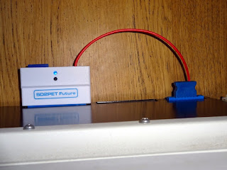
The divMMC future case has a cutout for a 9 way D joystick connector. That is not required here, so a blanking plate is used to allow the power input cable to exit (there is no power on the IEEE-488 connector, so 5V is tapped from the datasette in the same way it is done on the C64 SD2IEC).
With SD2PET CR renamed as SD2PET future, and the main stumbling blocks in the SD2PET
+ resolved. These went onto pre-order. I was told that everyone would go for the plus version, and we could quietly drop the future version when no one ordered it. But people did order it. It didn't sell as many as the plus, but enough to make it viable.
And then a request along the lines of '
can I use a standard BBC SD card reader on a BBC Master Compact?' turned into '
can you make me an SD card reader for a BBC Master Compact?', which turned into '
I could probably do quite a nice one in an SD2IEC case', which then turned into '
could you use that on other BBCs?', which turned into
SD2BBC.
That followed the same ideas as I have mentioned before, use the experience from previous designs and common parts and circuits where possible, so this took what I had learned from the SD2ELK, and the case and SD card power circuits from the SD2IEC. It did however mean that I was diverted from SD2PET again, and you may have noticed a run of blog post of BBC micro repairs in order to test this on a range of machines.
Of course, I've recently been doing the same thing with PETs, so expect a lot of upcoming PET repairs with one of these plugged into the side.
Due to a delay in the production side of the
SD2PET +, the
SD2PET future has arrived first. These are shipping now, with the plus version to follow as soon as we can.
Update:
The second batch of these has been built and it now shipping, a slight change has been made. The original batch (now #rare) has a black drive reset switch, and a clear button fixed in place above the indicator LEDs. The new batch now have a flush clear section above the LEDs instead.
These are also now available from my Tindie store.
2022 Update: The SD2PET future is now the main model, and is now just referred to as the SD2PET. Available now from The Future Was 8 bit