
This is the new version of the VIC20 Penultimate Cartridge, and you may notice something different. No more DIP switches. This one is menu driven.

I've been building a variety of cartridges for the VIC20 recently, from simple cartridge replacements to large ROM/RAM boards. This cartridge I had named 'The Penultimate Cartridge' as there seemed to be lots of revisions of Ultimate and Final Cartridges for this and other systems, so I thought I would be honest.

This had up to 35K of RAM (3K + 8K + 8K + 8K + 8K) and 32 ROM images (4K/8K/16K). These were selected by DIP switch. But that wasn't ideal, as they can be a bit fiddly for regular use, and you keep needing to refer to the list of settings. It would be nice if there was a way to set the choice without using the DIP switches, a menu system of some kind.

My initial thoughts were to use a couple of 8 bit latches to form simple output ports. These would be set by the menu software to change the switch settings, but that was going to get complicated. I did think about using something like a 6520 or 6522 which are dual 8 bit ports (and more), but they are quite large.

Instead, I went for a microcontroller. In the prototype, I chose an Atmel ATmega328P (as used in the Arduino Uno), although I am using the ATmega48PA in the actual cartridges. This is wired 'dead bug' style onto one of the previous cartridges. I built up a board without DIP switches and installed some LEDs for testing. Don't worry, this isn't the final version either (see, why it's Penultimate).

The microcontroller is there for a couple of reasons, it could be the pair of latches, with enough inputs and outputs to replace the DIP switches. I used the final address line available on the 32 pin ROM socket, so I could go up to a 27C080 EPROM with 64 ROM images, although I'm sticking with 32 at the moment. I also wanted to be able to preset an option for these and I needed it to be able to reset the VIC20 to read in the new cartridges.

What was a reset button on the original became a menu button. Pressing this puts the VIC20 into reset, switches the mode and the ROM address to select a menu program in ROM and then takes the VIC20 out of reset to boot up the menu ROM.

The menu program would then allow the user to select their option and would change the switch settings appropriately. This would be poking a number to an IO address mapped to the cartridge slot (I used 0x98xx). When this happened, there is a short pulse on the relevant enable line. It wasn't initially working, so time for the logic analyser again.

Even running at 16MHz the microcontroller didn't respond fast enough to that on an interrupt pin, so I had to change it to poll that pin in a loop. It hasn't got anything better to do, so it just sits there polling the input pin. Now it was time to write the menu program.

This was my first attempt, written in BASIC and loaded from disk. This proved the principle, it worked. Now I just needed to get that working as a cartridge. It's been a while since I wrote code for a 6502 system. I wrote loads for the BBC micro back in the day, but not much recently. There was little information on the necessary magic to convert some C or assembler into a cartridge, but I was pointed at some sample code (thanks to Stefan Vogt).

I though, oh, that's nice, there's some double width fonts in there for the titles. Then I remembered I was on a VIC20, and that was the normal font. It took a while to be able to build that as the code was lacking any information on the settings required to build it, and there were errors in some of the files. But it was the information I needed and I got it working and I was away. As someone who writes a lot of code, you get used to certain development environments. I was testing out cartridge code initially with notepad++ text editor and cc65 on the command line. I was pointed at the Atom IDE, but it didn't work for me, so I went back to Microsoft Visual Studio.

I set this up as a makefile project, but without a makefile, and just a command line to compile all the .c files in the project. That worked nicely and I could just type away with nice syntax highlighting, my usual source control (SVN) and all the tools of my usual IDE.

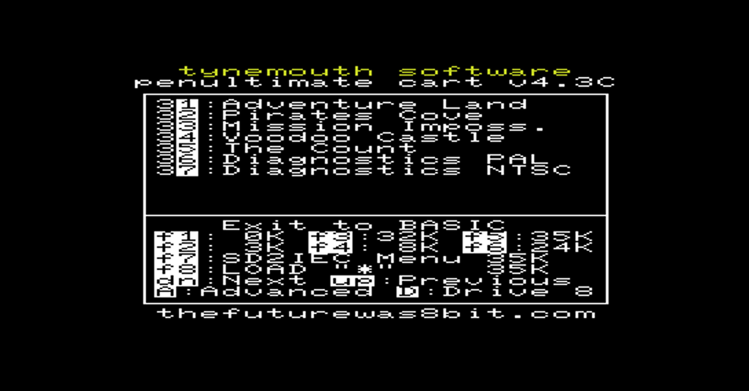
The main menu turned out to be fairly simple to do, just build up a list of the cartridges on the ROM, and which mode and address they need and present the menu to the user. I tried to make this as simple to use as I could and went for numbered entries, a page at a time, rather than scrolling down through a long list.

This is an early version of the menu. Red is always a difficult colour on a PAL system, and it didn't come out well, so I changed it to yellow later on. There were three elements to this, a list of ROM cartridges that could be started immediately as if the real cartridge was plugged in, a list of memory options to act as a RAM expansion, and the option to boot straight to a filebrowser or the default program on a disk.

I added an 'Advanced' menu with just RAM options, to give all the combinations of RAM available from unexpanded, up to 'all banks' which gives a total of 35K additional RAM. The cartridge and the RAM were easy, as these were just a case of poking the mode and address to the cartridge. I wanted to include some of the Scott Adams text adventures (OK, well all of them), on there, and these have an odd quirk in that they do not automatically start. The cartridge case reminds you that you need to type SYS 32592 to start the adventure. This isn't ideal, I'd like to make those automatically start. How hard can it be?

Well, quite difficult it turned out. The cartridge uses two 8K block, but neither in block 5, so it doesn't auto start. Apparently it was so full of code there wan't space for the loader code. What I was thinking was just setup the ROMs and then jump to address 32592. That doesn't work for two reasons. One, as soon as the cartridge ROM settings are changed to page in the game ROM, the currently running code which was about to run JMP 32592 is no longer there. To get around that I had to jump through quite a few hoops. It was a very interesting process picking apart the VIC20 memory map and kernal ROM disassembly to see how it all worked. I needed to create a small chunk of code which would switch the mode and then run the game. This needed to be copied to somewhere in memory where it wouldn't be affected when the cartridge mode was changed. I identified the cassette buffer would be suitable. This is 192 bytes at 0x0340 - 0x03FF.

I wrote the code, in 6502 assembler, that would do the switch and the code to copy it to the cassette buffer and run it, but it didn't work. This was the second reason, it appears it needs quite a bit of the BASIC initialisation to happen before it will run. A bit more reverse engineering later, and I had it running bits of the kernal initialisation code and then jumping to the ROM. This also hit problems, as BASIC initialisation very thoughtfully cleared the cassette buffer, and obliterated the code that was running. The second time this code has had the bits pulled out from under it's feet. To get around that, I wrote a modified version of the BASIC initialisation which didn't clear the cassette buffer and finally that worked. You can now select one of those and it will automatically start. A lot more effort that just typing 'SYS 32592' every now and then, but I like an interesting challenge.

The next challenge was to automatically load and run a program from disk. How hard can that be? Yes, you guessed it, quite tricky as well. I was thinking this would be a good companion to an SD2IEC disk drive replacement, being able to automatically start it's file browser.
To do that, I had to change the memory mode of the cartridge, and again, the running code disappears. The same solution worked out here, create some code to do the memory mode change, load and run the program, and run it from the cassette buffer. Again duplicating the BASIC initialisation code, a bit further this time, and again writing in assembler. It all came back to me thirty years later, and by the end of this I was hand assembling it to create the array of bytes in the final code.

It took quite a while to work out what combination of calls kernal code were required to setup and load a file, reparse and finally execute it, but I was rather pleased when my test program was finally loaded from disk and run automatically from the cartridge menu program.

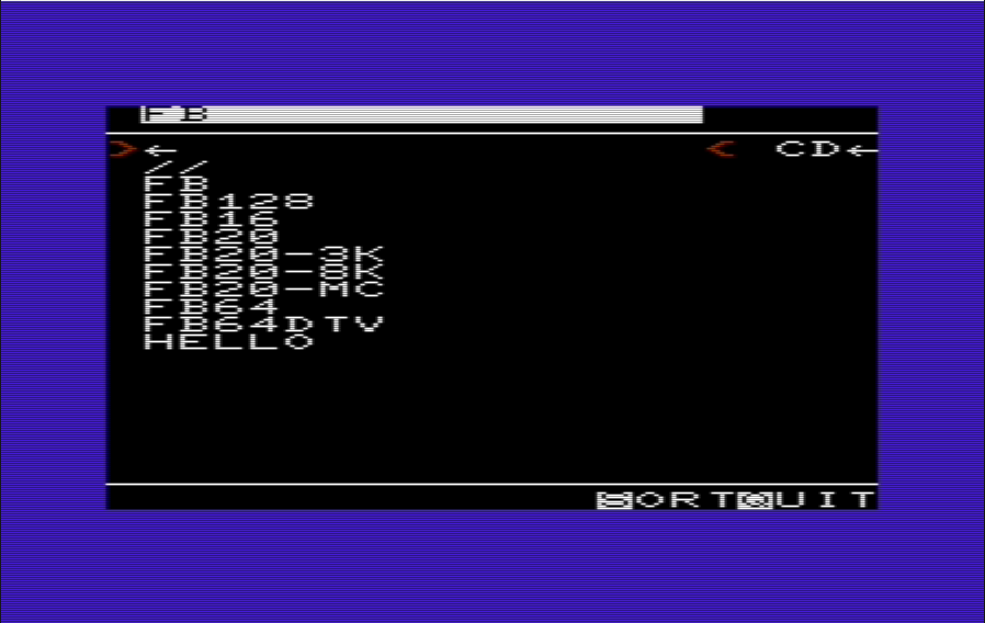
Due to the convoluted nature of the memory MAP on the VIC20, there are several versions of the file browser, so I choose the appropriate one to run based on the amount of memory selected. Yes, there is the FB program which will detect the amount of RAM and run the right program, but why add the extra step.

With that coding finished, it's now feature complete. At the last minute, I've added in drive number selection, press D to cycle through 8-9-10-11 and back to 8.

So there it is the finished VIC20 Penultimate Cartridge. There are a few things I might add to it, such as joystick support, and maybe an integrated file browser, but that's it for the moment. I've been testing this on a standard PAL VIC20-CR. This will probably not work if you have any internal RAM upgrades already fitted to your VIC20. I am awaiting results of testing on an NTSC VIC20.
Update:
It works fine with Jiffy DOS KERNAL, which is noticeably faster accessing the SD2IEC. Testing with the VIC20 port of Doom as that uses all 35K of RAM. Normal KERNAL: 10 seconds to load file browser, 60 seconds to load Doom. Jiffy DOS: 2 seconds to load file browser, 11 seconds to load Doom.

I've made the PCB in the same format as the previous ones, so that it will fit into an existing cartridge case. Here I've used a dead Comic Cruncher cartridge that looks to have been left out in the rain or something. All corroded and a peeling label.

I removed the label and the corroded PCB and stuck on a label sent to me by Mike Robertson, who made it for his Penultimate Cartridge.

This goes well with one of the nice SD2IECs from thefuturewas8bit.com, here is my modified cartridge next to a VIC20 coloured SD2IEC.

This all fits together nicely with the VIC20 to give you access to
31 39 ROM cartridges directly, or as many carts and D64 images
as you can fit on the SD card int the SD2IEC (which is all of them, many times
over).

You can buy one of these VIC20 Penultimate Cartridge boards now, programmed
and tested. You can use it as a bare board or fit in a spare cartridge
case.

UPDATE 1:
I've managed to squeeze more cartridge images into the ROM by doubling up the 8K cartridges. I had considered this with the DIP switch version, but didn't have enough switches. Now it's under software control, I can fit two 8K images into each 16K bank and address them separately, so there could be up to 62 8K carts on the standard, or 31 16K carts, or a combination of both. There are now 37 cartridges on the menu, and space for a few more.


UPDATE 2:
I've added support for joystick navigation to the menu. Up and down moves within the displayed page. Left and right change page. You can also scroll down onto the next page. Fire loads the ROM.

I've also added some disk commands before loading the SD2IED file browser. It will now change out of a disk image (if one is loaded) and back to the root, where the file browser lives.

A few cartridges have been added, taking the total to 39. There is still a bit of space free for a few more.

UPDATE 3:
The firmware has been updated to
v5.0a, with the total up to 43 ROMs. The uncased versions are still available above.
The custom cased versions are now available to preorder now
from www.thefuturewas8bit.com.

UPDATE 4:
There is a user guide if you need any further information.

UPDATE 5:
The first run of cartridge is now here, more photos of those and the test program.

UPDATE 6:
These are now in full production in custom injection moulded cases and can be purchased from The Future Was 8 Bit.

Penultimate Update:
The production version of the Penultimate Cartridge is now available from The Future Was 8 bit


