This is an old post, preserved for reference.
The products and services mentioned within are no longer available.
This seems to be quite a common fault throughout the range of Commodore PET machines, so I thought I would roll up several repairs into a single post.
On power on, you get a screen full of characters, and there is something that looks about right, but all the letters look wrong.
If you look closer, you can see that in this case, the numbers and some of the letters are right. This is what it should say.
Now we need to do a bit of maths. First you need a table of the PETSCII character set (which is not quite the same as the ASCII one). This screen is generated by my PET Diagnostics board, and is quite handy for this.
Look up the values of some of the characters which are displaying correctly and incorrectly and look for a common factor.
Expected
|
Hex
|
Binary
|
Displayed
|
Hex
|
Binary
|
R
|
12
|
0001 0011
|
R
|
12
|
0001 0011
|
E
|
05
|
0000 0101
|
U
|
15
|
0001 0101
|
A
|
01
|
0000 0001
|
Q
|
11
|
0001 0001
|
D
|
04
|
0000 0100
|
T
|
14
|
0001 0100
|
Y
|
19
|
0001 1001
|
Y
|
19
|
0001 1001
|
3
|
33
|
0011 0011
|
3
|
33
|
0011 0011
|
*
|
2A
|
0010 1010
|
:
|
3A
|
0011 1010
|
From that it can be seen that the characters all being displayed all have bit 4 set, even the ones that shouldn't have bit 4 set. So the RAM chip which stores bit 4 is faulty (or sometimes the buffer that writes into it, or the latch which reads out of it).
On earlier 40 column machines (usually the ones with 9" monitors), there are two 2114 RAM chips. One handles bits 0,1,2 and 3, and the other bits 4,5,6 and 7.
Later CRTC based 40 column machines, there are two 2114 chips next to the empty spaces where the 80 column circuitry would go.
On 80 column machines, all four RAM chips are populated. Each pair handling alternate characters, so if you have the same bit 4 fault on an 80 column machine you would see alternating faulty characters.
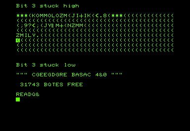
You can see the first, third, fifth etc. characters are all correct, and the second, forth, sixth etc. have bit 4 stuck high as above.
I have written a program to simulate bit faults in the video RAM:
You can also see whole RAM chips failing, so you all four bits in the upper or lower nibble are stuck.
Finally, if both RAM chips are faulty, you get a nice chequer board pattern or a screen full of @'s.
The 2114 RAM chips used on most PETs are still available, but the 6550 RAM chips used in some of the earliest 2001-8 models are more difficult to locate. You can just see them under the dust.
This 2001 appears to have one dead chip, you can see the same O's and /'s pattern in the simulations above.
Swapping the chips around shows the opposite problem, so it is definitely a faulty chip.
I have built a module which can plug in and replace both of those chips.
I haven't listed these for sale, but if anyone needs one, let me know.
In this case, once the display was working, the RAM count was short, one of the main bank of RAM was faulty.
The spare working video RAM chip was used and the full 8K restored.
It is worth noting that a common fault on the 6550 RAM chip is the enable lines, there are several of them and the seem to fail in a way that enables the chip all the time, drowning out or fighting with whichever other chips should be active at the time.
When used as video RAM, the enables are not required, so you can sometimes shuffle the chips around so the ones with faulty enable lines are used as video RAM. I didn't have any spare dust to reapply to these chips.
Here is the same sort of fault, this time on a TRS80 Model I. Unusually, it only affects part of one line, which is showing '£' characters.
The characters all work when typed anywhere else on the screen, just the £ sign appearing on the end of that line.
Typing into that area shows characters are being modified, and the space is being shown as a £, in the same way as the space on the PET was shown as @ or / etc. depending on the fault.
Expected
|
Hex
|
Binary
|
Displayed
|
Hex
|
Binary
|
q
|
31
|
0011 0001
|
1
|
71
|
0111 0001
|
r
|
32
|
0011 0010
|
2
|
72
|
0111 0010
|
space
|
20
|
0010 0000
|
£
|
60
|
0110 0000
|
*
|
2A
|
0010 1010
|
j
|
6A
|
0110 1010
|
These all point to bit 6, which on the TRS80 is a bit unusual as the video RAM is made up of 7 chips with bit 6 unused. Later an eighth chip for bit 6 was bodged on with a piggy back chip.
With that replaced, the TRS80 was back to normal.
Whilst on the subject of video faults, I may as well mention another few oddities. This PET showed only a flashing white cursor, which moved around as you types, but no characters.
This was down to a dead character ROM.
The character ROM is also to blame if you get characters that aren't quite right, such as the extra bar on the E here.
On most PETs, a 27C16 or 2816 can be used, but for 2001-8's with 6540 ROM chips, I have an adapter.
With that, the video RAM replacement and a ROM/RAM board, you can get rid of all the 6540 and 6550 chips and have a 2001 PET which should be considerably more reliable (and less than half the power consumption).
A permanently inverted picture can be caused by a few things, it bit 7 fault can do that, but in this case it turned out to be a 74LS74 flip flop.
The same machine also developed a screen which was full of stripes, even with the character ROM removed, so that was narrowed down to the 74LS165.
Both replaced and the machine is back to normal.
I think that's about all I can say about video faults on the Commodore PET. Congratulations if you got this far, by the way.