Sunday 24 September 2017

Commodore PET - digital tape counter repair

This is an old post, preserved for reference.
The products and services mentioned within are no longer available.

An unusual 2001 has come in for repair. The first things which stands out is the button and display bezel cut into the front panel.
Inside, there are some extra boards at the side of the PET.
There are two boards, one is a commercial counter board from RS, the other a homemade power supply.
It taps power from the transformer, to generate it's own 5V rail. Probably a good idea as the PET is often pushing the limits on it's regulators.
The counter board (RS part number 434-239 - discontinued) contains an RS badged ZN1040E (RS part number 306-285 - discontinued). I did find a datasheet for the ZN1040E.
The ribbon cable connects to the display mounted in the case.
It's not an hour meter, as there is a mechanical one on the back of the PET, currently showing 1,209.1 hours of operation for this PET (since the hour meter was installed anyway).
Tracing the wires from the counter board, it doesn't connect to the PET itself, it goes to the tape deck. Inside the tape deck, I found some more unusal modifications. Oh right, it's a tape counter.
The main drive belt had come off, and snapped as I was removing it, as it was quite brittle. They usually need replacing anyway (TFW8B sells them).
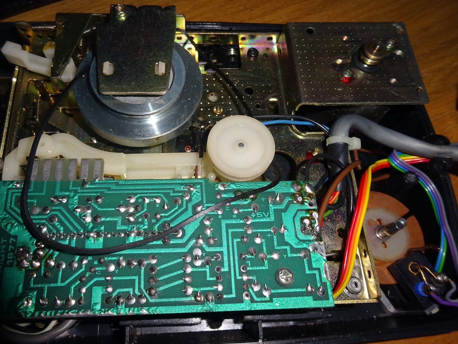
At the top there is a wheel with four slots cut out and an optical sensor. This will give four pulses for every rotation of the wheel. Wow, quite an impressive amount of work has gone into this.
This also had a belt which appears to have partly melted as it looks like it was an elastic band, rather than a rubber belt.
That looks like it went around the tape spindle, which appears to have been designed to take a belt drive.
Yes, I had a look at a later VIC20 datasette which is based on the same tape mechanism as the black PET version, but has a rather simpler tape counter built in. Simpler, but no where near as nice.
At the front, there is a microswitch which senses when the rewind switch is pressed, so it can count backwards. Rather near really.
The tapedeck at least isn't RS, Commodore part number 320109.E (Discontinued).
OK, that's the belt's replaced, let's give it a go then.
When powered on, 5V is present, but there is nothing on the display.  Probing around, none of the outputs are moving, the chip appears to be dead. The inputs looked correct, a pulse when the spindle turns, rewind sense working, no reset or disable pins active.
I looked around for replacement chips. I found 'untested' ones for £50, so decided not to go down that route. I did consider removing those boards and installing an Arduino or something like that to drive the display. But it would be a bit of a shame to lose the original boards.
Never fear, I have the datasheet, which includes a schematic of the actual board fitted to this PET. This contains all the drive transistors and resistors for the display etc. so all a replacement would need to do is set some lines high or low to multiplex the display, so let's build a replacement.
I have based this on a PET diagnostics PCB, which is effectively a breakout board for the microcontroller on board to allow it to drive the PETs address and databus etc. Here I've aligned the 28 pin socket so the display segments are all on one 8 bit port.
With than in place, just a case of writing some firmware. I didn't bother implementing all the features of the chip, just those required in this application. The full chip could be emulator and a custom 28 pin board designed, should there be a market for a ZN1040E replacement - let me know if there is. I started with a simple test of the multiplexing and the LEDs, display 8888.
Powering that on, I found that not all of the displays were working. Some of the segments were flickering, the end one was particularly bad and there were some flickering segments on two of the others.
The display board is another RS part (434-239 - discontinued). I moved the two best display to the right hand side. Writing the remaining code was fairly simple, two interrupts. A timer interrupt to handle the display multiplexing, and a pin change interrupt to increment or decrement the counter.
The switch also causes and interrupt, and resets the tape counter to 0. I initially started with 0000, but changed to hiding the leading zeroes so the bad displays were less obvious.
That all seems to be working nicely, apart from the duff displays.
The PET board was another issue, more on that in another blog post, but that is now working as well.

Update:

The LED modules were, of course, RS branded, 586-526 (discontinued).
 I had a look around and found some modern ones with the same pinout and digit size.
I replaced all of them as they were all getting a bit intermittent. They all worked nicely, and you don't see the grey background through the red tinted display window in the case.
With the new LEDs fitted that's all back in working order.

Saturday 9 September 2017

Commodore 64 Cartridge Cases and PCBs

This is an old post, preserved for reference.
The products and services mentioned within are no longer available.

You may have seen there are some new Commodore 64 cartridges cases appearing from The Future was 8 bit.
These are shorter than the traditional Commodore 64 cartridge, so these new cases are referred to as 'Stumpy'.
The boards inside many of the Commodore cartridges did not make use of the larger size case anyway, as the PCB only contained a single ROM chip.
The first use of these was replacing the case for the Epyx Fastload Reloaded cartridges.
You can see the smaller case is still large enough to read the label and to grip onto to remove it from the C64.
But you can now buy an empty cases with a PCB to make your own cartridges. The photos in here show a few revisions of the PCB, but all are effectively the same.
The ROM or EPROM chip used can be anything from a 27C64 with a single 8K ROM image, up to a 27C512 with 8 different images on that can be selected using links on the PCB.
In most cases, just copy the 8K ROM image into the top 8K of whatever ROM chip you are using and leave the links in their default configuration of all wired to 5V (see the thin PCB tracks making that connection). If you want a bit more information, see below.
There is not quite space in the cartridge to install an IC socket, due to the dimensions of the Commodore 64 cartridge slot, so EPROMs need to be soldered directly to the board.
If you are planning to make several of these, I found it useful to get an extra PCB (these are available separately) and fit a socket and some jumpers to test things out before committing to soldering.
As a side note, we did try an option of using extra large holes, to allow a turned pin socket to partly sink into the board. This did work, you can see the socket in the top is now sitting flush with the board, with more of the pins sticking through. The production boards have normal sized holes, so the ROM chips will need to be soldered in place.
There is space on the left to fit a 100nF through hole axial ceramic decoupling capacitor, on the latest PCB, you can alternatively fit a surface mount 1206 capacitor if you prefer.
The other jumpers on the board set when and where the ROM image will appear in the Commodore 64 memory map. As with the address jumpers, these are pre-wired. If you want to change these, or fit jumpers, you need to carefully scratch the existing connections between the pins, and solder a wire link between the pins you want to connect.
The latest PCB design moves these jumpers to the top right, and separates Game and ExROM, but the function is the same.
Game and ExROM both set flags that the Commodore 64 reads to determine how to deal with the cartridge. Normally one or the other is set. The CS jumper selects if the ROM will use the ROM_L or the ROM_H select line. The table below shows the memory map of the Commodore 64, and where the ROM chips live. The entries in brackets indicate where an optional second 8K ROM could go.

Address range
Normal Mode
Game
Ultimax
C128
F000-FFFF
Kernal ROM
Kernal ROM
ROM_H
Kernal ROM
E000-EFFF
D000-DFFF
IO / Char ROM
IO / Char ROM
IO / Char ROM
IO / Char ROM
C000-CFFF
-
-
-
-
B000-BFFF
BASIC ROM
(ROM_H)
-
ROM_L
A000-AFFF
-
9000-9FFF
-
ROM_L
(ROM_L)
8000-8FFF
-
7000-7FFF
-
-
-
-
6000-6FFF
-
-
-
-
5000-5FFF
-
-
-
-
4000-4FFF
-
-
-
-
3000-3FFF
-
-
-
2000-2FFF
-
-
-
-
1000-1FFF
-
-
-
-
0000-0FFF
-
-
-
-

Here are some example configurations.

Normal 8K Cartridge 

This is mode is used for many games, and the Commodore 64 Diagnostic cartridge. Here the link to Game needs to be cut and the link connected to ExROM. The CS link is on ROM_L, so the ROM is located in the address range 8000-9FFF.

UltiMax 8K Cartridge

This is used for older games designed for the Commodore Max console and for low level utilities such as the Dead Test cartridge. Here Game is linked and ExROM is open. The CS link is changed to ROM_H, so the ROM is located in the address range F000-FFFF, where it replaces the Kernal ROM.

Commodore 128 Cartridges

The Commodore 128 has a mode where both GAME and ExROM are open, and CS uses ROM_L. The ROM is mapped into a 16K block (although this cartridge will present the 8K ROM image at 8000-9FFF, mirrored at A000-BFFF).

ROM Address Selection

Normally, just write the 8K ROM image to the top 8K of the ROM chip. If you are using a .crt file, remember to remove the header to just leave the 8K of raw binary data. If you are using a 4K ROM image, either double it up to fill 8K, or place it in the first half of the 8K block.
All the supported EPROM types have 25 pins wired identically and 3 pins with some differences. It is these three pins which are wired to the jumpers. They are labelled using the designations from a 27C512 EPROM.

Jumper
Pin
27C64
28C64
27C128
27C256
28C256
27C512
A15
1
VPP
NC
VPP
VPP
A14
A15
A14
27
PGM
WE
PGM
A14
WE
A14
A13
26
NC
NC
A13
A13
A13
A13

If you use a chip larger than a 27C64, you can place multiple 8K ROM images in there, and select the appropriate one using the jumpers. This table shows the jumper settings which should be used to select the ROM image. Entries in brackets indicate duplicates due to not connected pins. '-' indicates do not use.

A15
A14
A13
27C64
28C64
27C128
27C256
28C256
27C512
0
0
0
-
-
-
-
-
ROM 1
0
0
1
-
-
-
-
-
ROM 2
0
1
0
-
(ROM 1)
-
-
ROM 1
ROM 3
0
1
1
-
(ROM 1)
-
-
ROM 2
ROM 4
1
0
0
-
-
-
ROM 1
-
ROM 5
1
0
1
-
-
-
ROM 2
-
ROM 6
1
1
0
(ROM 1)
(ROM 1)
ROM 1
ROM 3
ROM 3
ROM 7
1
1
1
ROM 1
ROM 1
ROM 2
ROM 4
ROM 4
ROM 8


Update:

The latest version of these boards have a revised layout which should make it clearer which jumpers are required.
Now with the appropriate jumper settings silkscreened onto the board.
These are available from The Future Was 8 bit.
There is also a 16K version in the works. Coming soon.

Update2:

New style boards now available.

2022 Update: More recent versions of the C64 cartridge PCBS are available from  The Future Was 8 bit