This is an old post, preserved for reference.
The products and services mentioned within are no longer available.
Inside, there are some extra boards at the side of the PET.
There are two boards, one is a commercial counter board from RS, the other a homemade power supply.
It taps power from the transformer, to generate it's own 5V rail. Probably a good idea as the PET is often pushing the limits on it's regulators.
The counter board (RS part number 434-239 - discontinued) contains an RS badged ZN1040E (RS part number 306-285 - discontinued). I did find a datasheet for the ZN1040E.
It's not an hour meter, as there is a mechanical one on the back of the PET, currently showing 1,209.1 hours of operation for this PET (since the hour meter was installed anyway).
Tracing the wires from the counter board, it doesn't connect to the PET itself, it goes to the tape deck. Inside the tape deck, I found some more unusal modifications. Oh right, it's a tape counter.
The main drive belt had come off, and snapped as I was removing it, as it was quite brittle. They usually need replacing anyway (TFW8B sells them).
At the top there is a wheel with four slots cut out and an optical sensor. This will give four pulses for every rotation of the wheel. Wow, quite an impressive amount of work has gone into this.
This also had a belt which appears to have partly melted as it looks like it was an elastic band, rather than a rubber belt.
That looks like it went around the tape spindle, which appears to have been designed to take a belt drive.
Yes, I had a look at a later VIC20 datasette which is based on the same tape mechanism as the black PET version, but has a rather simpler tape counter built in. Simpler, but no where near as nice.
At the front, there is a microswitch which senses when the rewind switch is pressed, so it can count backwards. Rather near really.
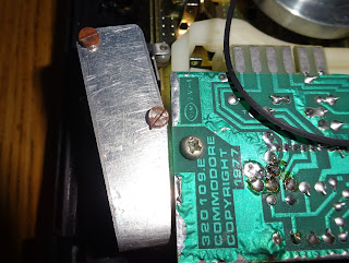
The tapedeck at least isn't RS, Commodore part number 320109.E (Discontinued).
OK, that's the belt's replaced, let's give it a go then.
When powered on, 5V is present, but there is nothing on the display. Probing around, none of the outputs are moving, the chip appears to be dead. The inputs looked correct, a pulse when the spindle turns, rewind sense working, no reset or disable pins active.
I looked around for replacement chips. I found 'untested' ones for £50, so decided not to go down that route. I did consider removing those boards and installing an Arduino or something like that to drive the display. But it would be a bit of a shame to lose the original boards.
Never fear, I have the datasheet, which includes a schematic of the actual board fitted to this PET. This contains all the drive transistors and resistors for the display etc. so all a replacement would need to do is set some lines high or low to multiplex the display, so let's build a replacement.
I have based this on a PET diagnostics PCB, which is effectively a breakout board for the microcontroller on board to allow it to drive the PETs address and databus etc. Here I've aligned the 28 pin socket so the display segments are all on one 8 bit port.
With than in place, just a case of writing some firmware. I didn't bother implementing all the features of the chip, just those required in this application. The full chip could be emulator and a custom 28 pin board designed, should there be a market for a ZN1040E replacement - let me know if there is. I started with a simple test of the multiplexing and the LEDs, display 8888.
The display board is another RS part (434-239 - discontinued). I moved the two best display to the right hand side. Writing the remaining code was fairly simple, two interrupts. A timer interrupt to handle the display multiplexing, and a pin change interrupt to increment or decrement the counter.
The switch also causes and interrupt, and resets the tape counter to 0. I initially started with 0000, but changed to hiding the leading zeroes so the bad displays were less obvious.
The PET board was another issue, more on that in another blog post, but that is now working as well.
Update:
The LED modules were, of course, RS branded, 586-526 (discontinued).
I had a look around and found some modern ones with the same pinout and digit size.I replaced all of them as they were all getting a bit intermittent. They all worked nicely, and you don't see the grey background through the red tinted display window in the case.
With the new LEDs fitted that's all back in working order.


