Sunday 30 June 2024

Annoying LCD Monitor Repair

I have been putting this off for a while, but it's finally time to get it sorted.

I run multiple monitors on my main machine, usually 5 or 6, a collection of old mismatched screens that suit me fine.

My favourite quote on the subject comes from the late, great Terry Pratchet - when asked "Why six screens?", his reply was "Because I haven't got enough room for eight."

As these are old monitors, they occasionally fail. And like most old monitors (and other consumer tech these days), they fail because of capacitors in the power supply.

At first they get slow to start, then sometimes they won't come on at all. This one has been going for a while, and it reached the point that it would start up after a few hours, and then be fine and I would just leave it on.

Now it is not starting up at all, so time to go through the hassle of detaching it from the mounting pole and fixing it.

After a bit of a fight getting the case off, lots of plastic clips etc., I got to the back of the panel.

The middle board is the power supply, and it is connected by cables to the pod on the right, the backlight inverter, and the one of the left, the video processor.

These cables are fixed at one end, and have sockets at the other.

Guess which end is soldered in place?

Yes, that's right, the one on the power board, so to get that out, I have to remove both cans and unplug the connectors inside. That involves also undoing the jackposts on the VGA and DVI connectors. Not a great design.

The video processor board at least confirms the date code at around 2003. Not bad, it is still a good monitor with a bright clear picture, so it is worth a bit of frustration to fix.

These connectors are in a bit tight, but it's finally freed.

Now for the backlight inverter.

Damn.

I was pulling the cable hard enough to pull the plug out, not a massive force, but it ripped off the entire connector before it unplugged from the socket.

So that's two things to fix.

Luckily it was all the solder that broken, no damage to any of the tracks. I put it back with far too much solder, to make sure in case I have to disconnect it again.

And back to the original problem.

Same old thing with LCD TVs and lots of other consumer tech of the day such as DVD players etc.

The good old bulging caps with domed tops.

I spotted a couple, all of the CapXon brand (well known for being a bit CrapXon).

There were various other green and brown caps around the board which looked to be OK. Just the black and gold ones.

There were four of those, and two had failed, so I thought it best to replace all of the same brand and age.

The smallest is marked 820uF and reads as, well, it reads as a resistor.

The next 1000uF cap reads as half that, and quite a high resistance.

The two taller 1000uF caps actually read OK, but it is probably best to have replaced them anyway.

I use 105°C rated low ESR capacitors, these have generally proved good replacements.

I didn't have an 820uF 10V, so I went up to 1000uF here.

The 1000uF 16V is a direct replacement.

I didn't have any 1000uF 25V caps, but they were wired in parallel, so I replaced the pair of those with a single 2200uF 25V caps. That's OK, right?

All the parts fitted, and you can see the permanently attached wires that made this job take twice as long as it needed to.

And now all back together and working fine. As expected, I've done dozens of monitors and TVs like this. I only write this one up as it was quite an annoying job that was made a lot harder due to some less that ideal design decisions.

The picture is looking really good in fact. The colours are brighter, the blacks are darker, the contrast is better.

Or in other words, I gave the screen a wipe over with a damp cloth when it was in bits.


Advertisements

I don't sell 20 year old monitors in my store, but I do have the full range of Minstrel and Mini PET kits and accessories.

UK and US only I am afraid, I can ship worldwide, contact me with your location and what you want. Sorry I have to keep saying that. I am working on an alternative.

All the links can be found here:

Patreon

You can support me via Patreon, and get access to advance previews of posts like this and behind the scenes updates. These are often in more detail than I can fit in here, and some of these posts contain bits from several Patreon posts. This also includes access to my Patreon only Discord server for even more regular updates.

Sunday 23 June 2024

New Commodore 16 internal 64K RAM upgrade

I have converted many Commodore 16's to Commodore 64s 64K Commodore 16s, and wrote quite a detailed post showing various methods. ( http://blog.tynemouthsoftware.co.uk/2019/02/commodore-16-64k-upgrades.html)

All of these involved removing the two 16Kx4 dynamic RAM chips and replacing them with two 64Kx4 RAM chips. 4416 to 4464. And modifying the multiplexor chips to add the two missing address lines.

The problem is, it's not that easy to get hold of those 4464s. They are used on the Amstrad versions of the Spectrum +2/+3, the C64C and Atari XEGS amongst others.

On other systems with 64Kx1 dynamic RAM chips, 4164s, I have made boards to replace those with a single 64Kx8 static RAM.

The idea with the lower pin count dynamic RAM chips is there are two select pulses, RAS and CAS. One selected the row address (8 bits) and the other the column address (8 bits), making the full 16 bit address.

To use a larger pin count static RAM ICs, the row address is first latched in on the RAS pulse, and then when the CAS pulse comes along, a combination of the previously latched row address and the new column address is used to make the full 16 bit address.

That works nicely on various systems I have made those for, e.g. this for the Spectrum 128K +2, which uses two of those boards.

I wanted to make one for the Commodore 16, but I thought I could try a slightly different approach. 

The multiplexor chips that take A0-A13 and generates the row or column addresses are right next to the RAM chips, so I thought I could maybe cut out the middle man and skip the multiplexors (which drops it down to 8 bits) and the latch (which brings up back to 16 bits) and just have the RAM chip (well, plus one logic gate).

So I built up a board which taps all the address lines and data lines from the four sockets and wired them direct to the RAM chip.

The board has four IC pin headers on the back which plug into the four sockets on the C16 board.

The four ICs, two 74LS257 multiplexors and two 4416 DRAM chips are carefully desoldered. (and I mean carefully. This is job for someone with the right tools and experience to desolder the chips leaving the board and the chips undamaged)

I should make that caveat larger.

DESOLDERING EXPERIENCE REQUIRED - NOT FOR THE BEGINNER

And whilst I am adding caveats.....

DO NOT BLAME ME IF YOUR COMMODORE 16 DIES WHILST USING THIS

I will supply four turned pin IC sockets with the kit, those are then soldered in place.

The best way to test this is to install the four chips that have just been removed. If you cut the legs off the chips to desolder them, then this kit is probably not for you.

That should still operate as a 16K Commodore 16.

Time to remove those chips and install the new module.

The multiplexor chips only have 14 address lines, so as with the other upgrades, A14 and A15 have to be tapped from elsewhere. I added jumpers to allow those to be selected, or disabled to go back 16K, should that be required for compatibility at any point (I am not aware of any games that will fail due to too much RAM).

As described in the previous post, a good place to get those is two vias next to the modulator.

A two pin header can be fitted there for ease of installation.

In addition, the clock line also needs to be tapped. There are various places this can be found, I went for one of the vias next to the PLA. Again a pin header is fitted.

That is the shorter wire marked phi 0.

A14 and A15 can be fitted either way around, but this is the correct orientation.

All the cables, connectors and sockets will be supplied with the kit.

OK, that's everything installed, checked and double checked.

Time to switch on.....

Excellent. Let's give Diag264 a run.

Should you ever want to go back to 16K, you can adjust the jumpers to the left.

Although, as I said, I can't see why you would need that.

Time to try out some 64K only programs from the plus/4 catalogue.

CBM command needs more than 16K, so I couldn't run it before on this machine.

And since I used it last time, I will try Icicle Works again.

All seems good, the kits are now available in my store.

Stop Press - new video from Tim's Retro Corner showing installation and testing of the kit.


Advertisements

The kits are now available in my store if you are in the UK or US. If you are elsewhere, contact me as I can ship worldwide.

"DO NOT BLAME ME IF YOUR COMMODORE 16 DIES WHILST USING THIS"

"DESOLDERING EXPERIENCE REQUIRED - NOT FOR THE BEGINNER"

The store also contains the full range of Minstrel and Mini PET kits and accessories, again contact me if outside the UK or US. Sorry I have to keep saying that.

All the links can be found here:

Patreon

You can support me via Patreon, and get access to advance previews of posts like this and behind the scenes updates. These are often in more detail than I can fit in here, and some of these posts contain bits from several Patreon posts (they also got an extra post covering the development of this board). This also includes access to my Patreon only Discord server for even more regular updates.

Sunday 16 June 2024

Repair Parts for Commodore PETs

Over many years of repairing computer like the Commodore PET, I have designed various little boards to replace unobtainum parts, or assist with diagnostics. I get occasional requests for these, so I thought I should list them properly.

Some of those will be well known, such as the PET ROM/RAM and the SD2PET. I will put links to all of those at the end of the post.

PET 6550 Video RAM Replacement

One of these I use a lot is the 6550 Video RAM replacement. Early Commodore PETs used their own MOS ROM and RAM chips, rather than standard tried and tested parts like the 2114 SRAM and standard mask ROMs.

The design of these was an interesting idea that worked differently to the standard parts.

This section grew into a post of it's own. Read all about the MOS 6550 RAM chip here - http://blog.tynemouthsoftware.co.uk/2024/06/mos-6550-ram-chips.html

TLDR: They fail, overheat and start to damage other parts on the boards. If you have a board with 6540s and 6550s, I would strongly recommend removing them and using a PET ROM/RAM board instead.

I designed a board which can be used to replace the video RAM with a modern RAM chip, which means you can preserve any working chips you have and have a cool running stable and reliable machine.

I later revised that to use larger footprint packages that were easier to produce.

And that is the version I have been using.

And the version I have now listed on SellMyRetro.

Assembled and tested and ready to go.

The pins fitted should be suitable for most sockets, and have worked on all the boards I have used these on. I have not needed to replace any of the sockets, and you are unlikely to find 22 pin 400 mil spacing replacement sockets, so if you need to, you would have to use socket strips or solder the board directly to the PCB.

2114 Video RAM replacement

Later PETs used 2114 video RAM. This is much more reliable, but does still occasionally fail, so I have a board that can be used to replace that. The PET video circuitry, particularly the later CRTC based machines, is very picky about RAM timings, and it can sometimes be difficult to find a set of vintage new old stock 2114 chips that work in this situation.

The board is designed to replace 2x2114 static RAM chips used as video RAM on most PET models.

This one is a straight swap. No timings or gating or select issues to address.

That works well on the 2001N machines as above, and is also be usable on 4000 and 8000 series machines. A 8032 has four 2114 chips, so you would need two of these boards.

The 4032 uses the same board with only two of the RAM chips populated.

The spacing is correct for the video RAM on these machines

It could also be useful anywhere there are pairs of 2114 chips with this spacing, although I haven't found any yet. The ZX80 and VIC 20 CR are too close together and the ZX81 is too far apart. The 2 pin VIC has the right spacing, but the pairs are vertically aligned, not side by side. So just the PETs for the moment.

These are available built and tested:

PET 6540-010 Character ROM replacement.

The character ROM on early PET 2001s is a 6540 ROM (6540-010). Later PET 2001s moved to a mask ROM (901439-08).

The PET Character ROM replacement does two jobs. Firstly, it can be used to replace a faulty 6540-010 ROM chip.

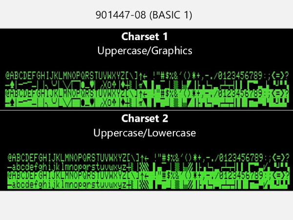
Secondly, it allows you to select between two character sets. If you use a PET ROM/RAM to upgrade to BASIC 2 or BASIC 4, this will be the correct character set. BASIC 1 is of limited use due to various bugs, but if for some reason you want to do that, you can select the original character set using jumpers under the ROM chip.

The 6540-010 was the character set for BASIC 1, the one which seems to be a more sensible arrangement. The uppercase characters remain the same in graphics or text mode and you get lowercase characters or more graphical characters in the other mode.

For reasons lost in the mists of time, they reversed that for BASIC 2, and kept that less logical arrangement for BASIC 4. When you move to the other character set, lower case is the norm, and the upper case is moved to where the graphics were. (this is why the 8032 etc. with business keyboards have "ready" prompts and 4032 and other graphics keyboard machines have "READY" prompts)

The board and ROM are available assembled and ready to go.

PET Video Out

I seem to have produced lots of these over the years in various shapes and sizes.

The earliest plugged into the userport and datasette port (for power). I used that for a long time on my PET 2001 test board, but it's not ideal as it blocks the userport for other things, although there is a passthrough for the datasette.

In the end I wasn't happy to sell that as it was quite a job to remove, and it might be possible to damage the edge connector if you go at an angle instead of straight backwards.

I did a version as two boards. Not sure what happened to that. I think a few of these things just came along at the wrong time when I was having problems with selling things online.

I also had another version at the same time, and I think that is the best one to go with.

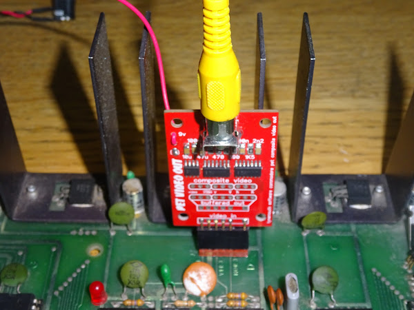
This one fits internally onto the monitor connector and gives you composite video. Well it gives you monochrome composite video in NTSC, slightly shifted to the right.

Even in PAL regions with 50Hz power, the PET video output is 60Hz. Many modern monitors support NTSC composite input.

Later CBM 40xx and 80xx models with CRTC based video circuits generate video at different frequencies, not compatible with most monitors, so this can only be used with 2001/2001N/30xx and 9" 40xx machines.

The board has a an onboard 5V regulator to avoid noise, so it need to be clipped to a 9V source, the polarity protection diode is usually an easy choice.

You then have all you need to get composite video out of a PET for bench testing.

The same diode can be used on 2001N boards, but it is a little more crowded there.

As always, available built and tested from my SellMyRetro store

Extra credit section

It is possible to use it on a CRTC based PET, but you need a custom edit ROM, and you need to change the jumpers to cope with the different sync polarity. I left space for jumpers to change this, but they are the sort I used at one point where I pre-wired the jumper with a PCB trace, so you need to cut that if you want to fit a jumper. It seems to work in this case as most users will just ignore the pre-wired jumper section and use it as is. There are also pads for a buffered video output with selectable polarity, but again, that is advanced users only. I may do another version with all that missing and just the standard composite output.

I could supply a version with the patched editor ROM.

But there are also two positions of the monitor connector, so it would need two versions. One in the middle of the board, for the earlier 8032 boards.

And one for the Universal Dynamic 40xx/80xx board where it is right at the bottom edge.

I think I started looking at these options in the past and just bailed out of the whole project as it got too complicated and there were too many options and someone always wants yet another different option. And then someone asks if it will work on a SuperPET and I just give up and delete the listing again. One of the reasons I haven't listed these sort of boards in the past is there are so many caveats about which machines are and are not supported, and a lot of people don't bother reading those and might end up with something unsuitable for their requirements.


Advertisements

This is the full list of links for those parts.

The links in these posts for US and UK customers. I can ship worldwide, so if you are elsewhere, please contact me with your location and the parts you need.

Or if you would rather a whole PET made from modern parts, the full range of Minstrel and Mini PET kits and accessories are available form my SellMyRetro store.

All the links can be found here:

Patreon

You can support me via Patreon, and get access to advance previews of posts like this and behind the scenes updates. These are often in more detail than I can fit in here, and some of these posts contain bits from several Patreon posts (they also got an extra post covering the history of my 6550 video RAM board). This also includes access to my Patreon only Discord server for even more regular updates.