
As part of something I was working on, I was looking into the ZX Spectrum divIDE, quite an old project, but a way of getting a disk interface for the Spectrum before the days of the divMMC.
The project this was for will probably not happen now (#Z80RIP) but I would still like to get this working.
I remembered seeing an all through hole version, and indeed I thought I had one at one point, but I couldn't find it. (Ed: I now remember it came in with a ZX Spectrum repair a long time ago and went back to the owner with the repaired Spectrum)
So, I had a look around for built units or kits, but all I found was someone selling bare PCBs on ebay. The divIDE 5.7C seemed to be the version everyone was using, so I ordered one of those.

I wasn't too impressed with the PCB. Just personal preference, but I don't like the way the PCB was marked out, quite difficult to follow. It may be ebay seller was just using a random set of gerber files they found online?

How on earth are you meant to work out what goes where?
Luckily, there is a schematic........
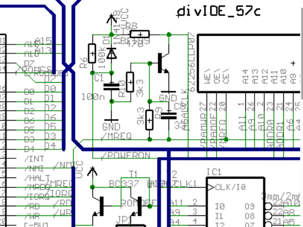
Oh dear, that's even worse.
All of the versions online seem to be variations of that. Some in colour, some not.
I finally found a better one thanks to Nightfall Crew.

Comparing that to what I could read from the PCB and the schematic it seemed right, and various photos online show built units with two missing parts (C8 and RN1) not fitted.

The only issue I had with parts was the BF199 transistor. I didn't have one of those and couldn't see any in stock at my usual suppliers. I instead used a BC548 which had similar (but slightly better) specs, but unfortunately a different pinout.
Fingers (and legs) crossed this minor bodge will work.

Looks fine, you would likely not spot it if you were not looking for it.

All populated and ready to go.

There is a 28C64B EEPROM on the board which needs to be programmed with the appropriate firmware using a program on the Spectrum.
You load up the program, then remove jumper JP2 (which is marked behind the jumper where you can't see it)

Lots of flashing bright colours as usual, seems to be going well.

And there it is flashed.

So I switch off, refit JP2 and turn the power back on but I don't get a boot screen, all I get is a copyright Sinclair screen?
OK, let's try that again.
No, same.
Hmm, there should have been a boot screen just like the divMMC.
Speaking of which, just to check, I tried going through the same process with a divMMC future, and that worked correctly.
I also tried FATware, an older firmware which should support the same hardware, that appeared to program correctly, but again did not work. I later retried it and at least got an error this time. Not sure what it means though.

I grabbed another Spectrum from the pile, in case the problem was with the two Spectrums I had been testing with. I was pretty sure it wasn't, since the divMMC worked, so I don't think it was a bad M1 line for example.
Trust me to pick one I hadn't updated.

Just needed a quick composite mod and a switching regulator replacement.

Lets retest with that.
Did it make a difference? No.
OK, lets' reprogram the GALs, and lets's also try a set of Atmel ATF22V10C as well as the Lattice 22V10B.

No, that hasn't helped.
OK, maybe my substitute transistor is not suitable?
I had to turn to ebay again I am afraid, but I got a pack of BF199s.

Being the correct part, that could be installed without the need for the twisted legs this time.

Did that fix it? No.
I have revisited this a few more times, trying different EEPROM and GAL chips and trying to program the EEPROM directly, but not getting anywhere.
I don't know what is going on there. It is possibly my build is bad, but I have checked over all the solder joints etc. and I can't see anything.
It is possible the PCB is bad, given the silkscreen mess, it is possible there are also errors with the traces.
It is possible I have the wrong GAL files, or my GALs are all bad, or my programmer is somehow not programming them correctly. (although I use the same chips and the same programmer for other things.)
Anyone got any ideas?
Anyone had any success building this version of the PCB recently?
Anyone got a working version of this I could borrow and compare?
Advertisements
The full range of Minstrel and Mini PET kits and accessories are available form my SellMyRetro store.

All the links can be found here:
Patreon
You can support me via Patreon, and get access to advance previews of posts like this and behind the scenes updates. These are often in more detail than I can fit in here, and some of these posts contain bits from several Patreon posts. This also includes access to my Patreon only Discord server for even more regular updates.
