Sunday 25 February 2018

Binatone TV Master 4 plus 2 (MK VI) Composite Video Conversion

This is an old post, preserved for reference.
The products and services mentioned within are no longer available.

Following on from the composite video conversion I did a few months ago on a Radofin tele-sports TV game, I have modified quite a few other TV games of a similar type.
I bought this one as it is the same model we had back in the seventies when we all looked just like the family on the box.
This one is a Binatone TV Master 4 plus 2, which is the same as the TV Master MK VI. This is similar to the original 4 game version (TV master MK IV), but with two additional games which use a light pen style gun.
The main unit on the 4 plus 2 is identical to the MK VI other than the label. The 4 plus 2 was a cheaper version where the light gun was an optional extra. The gun works in the same way as a light pen, and depends on the timing of the beam on a CRT screen to determine it's position. It will still work following the composite video conversion, but only on CRT televisions.
This is the black and white version, there was a colour version which looked almost identical but was marked 'Colour TV Game', and had white / grey box and buttons rather than the very 1970's day-glo orange. (date code on the chip is August 1978).
Inside is the usual General Instruments GIMINI AY-3-8500 chip, here as they often are in an unusual socket arrangement with no contacts on the four edge pins (they are used on later versions for 2 axis controls).
This was one of the few of these TV games I have found that didn't work. The sound was working, so it was playing, but I couldn't tune in the TV (even the old black and white portable I use for testing things with very poor video signals). The 'scope showed a valid composite signal entering the modulator section, so I just went ahead with the composite video out conversion, there seemed little point in repairing the modulator.
I tried something slightly different on this one, and fitted a header and a socket to the standard TFW8b composite video buffer board, that seemed to work quite well. The power was tapped at the bottom of the board, the video from the point it enters the modulator section, and the audio directly from the chip output.
The unit has a separate switch to turn off the internal speaker, so the audio is always fed to the TV set, but you can also turn on the speaker on the game itself if you want 'the full experience'.
Once powered up, there is a nice stable signal on the monitor, in glorious black and white.
The controls on this version are as simple as they get. One rotary control, and a mono 3.5mm jack.
An inside, one 1MΩ variable resistor. This one was was a bit flaky, but a squirt of contact cleaner and turn it back and forth a few times and it's now running fine.
Binatone like to put warnings on the back of these to get you to only buy their power supplies.
Is it regulated? Is it really? Looks like a standard unregulated linear power supply.
Well, I stand corrected. Yes that is a regulator. A bit rusty, but a regulator none the less.
A National Semiconductors LM342P-8.0, a bit like a 7808. This gives an 8V output which matches the case, although not the 9V the game specified, should be fine...
Time for some two player testing. The only time you will find football on my TV.

Sunday 18 February 2018

Minstrel ZX80 Clone Keyboard

This is an old post, preserved for reference.
The products and services mentioned within are no longer available.

I have added a new option to the Minstrel ZX80 Clone kits and builds, it's own keyboard.
This has been designed to match up with the Minstrel board, so it makes it almost a single board computer.
The Minstrel board itself remains ZX81 sized, the keyboard plugs into the keyboard connector on the bottom right.
These are mounted under the board. I am using 0.1" pin headers and sockets, and these will be supplied in the kits. You could use wire links, or even add cables and run the keyboard a short distance from the main PCB, a Minstrel-SK if you like.
There are a couple of unusual things with this PCB, both of which were done for aesthetic reasons. Firstly, there are no tracks on the top layer of the PCB.
The traces are all on the bottom. The keyboard is a matrix, the whole point of which is a set of rows cut across a set of columns with switches where they cross, you can see that here in the underside of a ZX81 keyboard membrane.
The obvious choice then is to draw the rows on one side and the columns on the other. Instead, I used a trick that used to be very common on matrix keyboards, but you don't see very often these days.
The tactile switches used have 4 pins, two sets of contacts wired in parallel, so in the above photo, the top two pins are actually the two ends of the same bit of metal. This means you can pass the signal through that wire link, and run another track underneath.
The green trace is on the PCB, the red is via the switches. You can see the blue column traces pass beneath the red lines.
This means you can lay the matrix out quite neatly on a single layer. This was done a lot in the 1980s when for large boards such as a keyboard, they could use a cheaper single sided PCB.
These days that is less of an issue, with the availability of cheap PCB production in small quantities, with boards coming in double sided with plated through holes, solder mask and silkscreen printing. The only slight problem I have is due to the volume of boards they produce like this, there is often a small code added to the silkscreen by the PCB manufacturer.
Sometimes they are kind enough to add these under a socket or an IC. But sometimes they end up in a really annoying place in full view on the assembled product.
I had an idea a while ago, but I had not had the right board to try it out on. My theory was they always put the code on the top of the board, so why not design it upside down? So I did.
This is actually the top of the keyboard PCB in the design files, and there they have stuck their code number. But when I get the board, I simply flip it upside down and have no annoying code number.
All I need to do now is design all my PCBs upside down. That can be quite challenging as it is mirrored, but in this case it was quite easy. This was my view in the PCB software.
However with anything more complicated, the mirroring would be confusing. I haven't looking into the format of the gerber files, but I presume it should be possible to write a bit of code to flip an existing board over. There's a coding challenge if anyone fancies it.
The new keyboard is available separately as a PCB or kit from my Tindie Store.
It is now an option on the main Minstrel ZX80 Clone kit Tindie Page, and also available as the Minstrel ZX80 Clone with Keyboard as a complete kit or assembled unit.

2022 Update: At the time of writing, there are still a few Minstrel 2 (ZX80) and Minstrel 3 (ZX81) kits available from  The Future Was 8 bit These have a version of this keyboard built in. They are the Final Edition kits, there are unlikely to be any more.

Saturday 3 February 2018

Keyboard options for the ZX Max 48 ZX Spectrum Clone

This is an old post, preserved for reference.
The products and services mentioned within are no longer available.

This is the ZX Max 48, a Sinclair ZX Spectrum 48K clone by Superfo (who also designed the Harlequin). Real Z80, ROM and RAM, and all the logic of the ULA in a CPLD.
It's a new product, I think still in development. I was contacted be a member of the Sinclair ZX World forum and asked to produce some keyboard overlays, in the same style as the ones ZX80 style overlays I do for my Minstrel ZX80 clones. He kindly sent a PCB and CPLD so I could build one.
Like the Minstrel, the ZX Max 48 board is designed to be the same footprint as the ZX81 (apart from the slightly larger edge connector and joystick port at the back).
This means it lines up nicely with the Minstrel keyboard (available from my Tindie store).
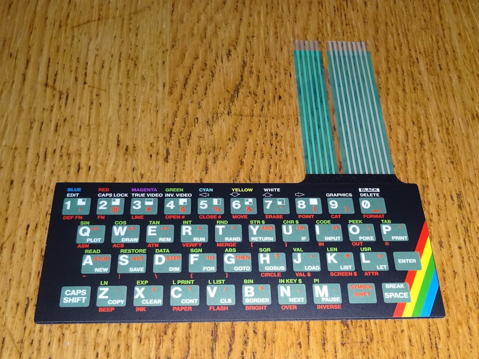
However, it was a keyboard overlay they wanted.
I designed this to fit over the ZX81 membrane, but with the ZX Spectrum keywords, symbols, colours and even the rainbow stripe.
Surprising how much smaller than a Spectrum it is, seems closer to the Horizons tape.
If you are using a ZX81 case which has a working membrane, you can stick the overlay directly over that.
Or you can get the overlays and  ZX81 membranes from my Tindie store).
The overlay sticks over a ZX81 style membrane.
You then get a ZX Spectrum style membrane, which can be installed in a ZX81 case.
Either way, you get a ZX81 with a ZX Spectrum style keyboard.
The ZX Max 48 board will fit inside, although you would need to modify the back of the case if you wanted to use the edge connector or fit a joystick port connector.
It's a sort of slightly smaller, slightly deeper Spectrum with a less rubbery keyboard.
You don't have to use a ZX81 case, you can just mount it on a board, or a sheet of perspex.
To do this, I fit the membrane connectors under the board, so the membrane tail is hidden under the board.
It's almost worth doing this just to admire the underside of the ZX81 membrane (this version designed and produced for me by RWAP).
It's not bad from the top side either.
So a complete new Spectrum, with mainly new bits (the NEC ROM chip in the above photo is original, as is AY-3 sound chip).
Well, I suppose I should fire it up now.
It almost worked first time. I got a result with the test ROM, but in monochrome. There are two oscillator circuits, one 14MHz which is divided down by the CPLD to generate the main Z80 clock, and also 4.43MHz which is for the PAL colour burst, but that wasn't running.
I found a similar problem on a Harlequin board I repaired. That had a dodgy 74HC04 chip. I tried a few others here, including the unbuffered version, the 74HCU04 (as used on the Spectrum +2). That didn't help, so I wasn't sure what the issue was. Might have been something up with the crystals I bought. I looked at other series resonant oscillators, and the capacitor value was generally larger, so I swapped out the 100pF for 100nF on the 4.43MHz side and it came to life.
The diagnostics was now in colour and all tests passed.
Back to the original ROM, and we appear to have a Spectrum.
10 PRINT 20 GOTO 10 had to be done.
Time for a bit more testing. Yes, that is a normal sized Zip Stik. And yes, that is a divMMC future.
This is a ZX Max 48 issue 2 board, which has a Kempston joystick port build in (and an AY-3 sound chip). The divMMC future also has a Kempston joystick, so I removed the 74HC366 chip to avoid any conflicts).
Only slight issue was the divMMC future board was a little high, luckily I had the perfect thing, not the usual sort of rubber feet, but it did the job.
Jet Pac ran nicely as did most of the other things I tested. There were shimmering lines in the graphics on a couple of games, I am told there is some updated firmware, so I'll give that a go.

The overlays, membranes, Minstrel ZX80 clones and keyboards are all available from my Tindie store.