Showing posts with label SD card. Show all posts

Sunday, 22 October 2017

Commodore 64 C Internal SD2IEC


The standard SD2IEC connected to the IEC port on a range of Commodore computers and replaces a traditional IEC disk drive such as a 1541. Sometimes it can be more convenient to have this integrated into the computer.
This is an SD2IEC Classic from The Future Was 8 Bit, which is all the functionality on a single PCB. I have previous described fitting one inside a Commodore VIC20 - VIC20 Internal SD2IEC.
This time, I am going to fit one inside a Commodore 64C. The procedure is much the same. Full pinout can be found on the TFW8B website. The are pins for power and data, and connecting buttons and LEDs etc.. For most applications, if you're not disk swapping, you can get away without the buttons, so we only need the 5 wires indicated below.
Three on the top, and two on the bottom (the 'Reserved' pin is not used, so can be ignored).
You can solder direct to these pads, but I prefer to fit a connector, here I used a 2x3 0.1" header.
There are various points you can connect this to on the C64 board, directly to the pins on the 6 pin DIN socket is the usual way, but I prefer to find somewhere I can connect on the top of the board. Tracking the pins back to a set of diodes, the three data lines can be located, Data on the junction of CR11 and CR15, Clock on CR12/CR16 and Attn on CR13/CR17.
Here I desoldered the diode leg at the appropriate point, inserted the wire and then soldered both in place. The power connections I took from capacitor C1 near the datasette port. You can do the same thing with the capacitor legs, but here I moved it to two via holes nearby.
Those wires are connected to a 6 pin connector and attached to the SD2IEC classic, which is fitted on top of the modulator box using foam pads.
The spacing works out nicely as the card sticks out over the cartridge port, but you can see from the side view there are no clearance issues.
The connector is clear of the other side of the modulator, so no issues with shorting out on it's case.
You might have spotted the case in some of these photos is actually a breadbin C64 case, not a standard C64C one. This is because I am currently doing some development work on a C64 cartridge, and the C64C has a bar over the cartridge port which blocks access to the ROM chip.
I have moved to the C64 case which doesn't have that bar, so I can continue development work with full access (I have also removed the cartridge shield, but you don't need to do that to fit the SD2IEC).
You can still use the original IEC port to attach other SD2IEC devices or real disk drives. The same rules apply as normal, make sure the device ID's don't clash. Most default to ID8, and most can be changed on the fly to one of the other addresses.
I have fitted these before in various C64C cases. The positioning of the board means the LEDs shine upwards. The C64C has thin plastic grills in that section of case. This means when accessing the disk, you get clear disk activity lights shining through the case.
You can take that further and use a clear C64 case, if you're into that sort of thing.

Thursday, 7 July 2016

VIC20 Internal SD2IEC


If you've got a VIC20 or a Commodore 64 and you want a simple disk drive replacement, the solution is fairly straight forward, you get an SD2IEC.
These are some very nicely packaged versions from The Future Was 8 bit, in a variety of shades to suit a range of Commodore machines.
These work well with the new VIC20 Penultimate Cartridge, which can automatically start the file browser from its menu.
During the development I have been borrowing a clear SD2IEC from my clear cased C64C.
And also a nice VIC20 coloured one on my main VIC20, made out of recycled VIC20 cases.
The VIC20 I was using for development wasn't one of my best. It arrived with one of those Commodore power supplies where the 5V was more like 7.5V, and many of the chips on the board had been fried. I had to replace most of the chips to get it running, but it's been a useful test machine since most of those chips were now socketed.
Something I've been meaning to do for a while was try out the idea of an internal SD2IEC, so I thought this would be a good candidate.
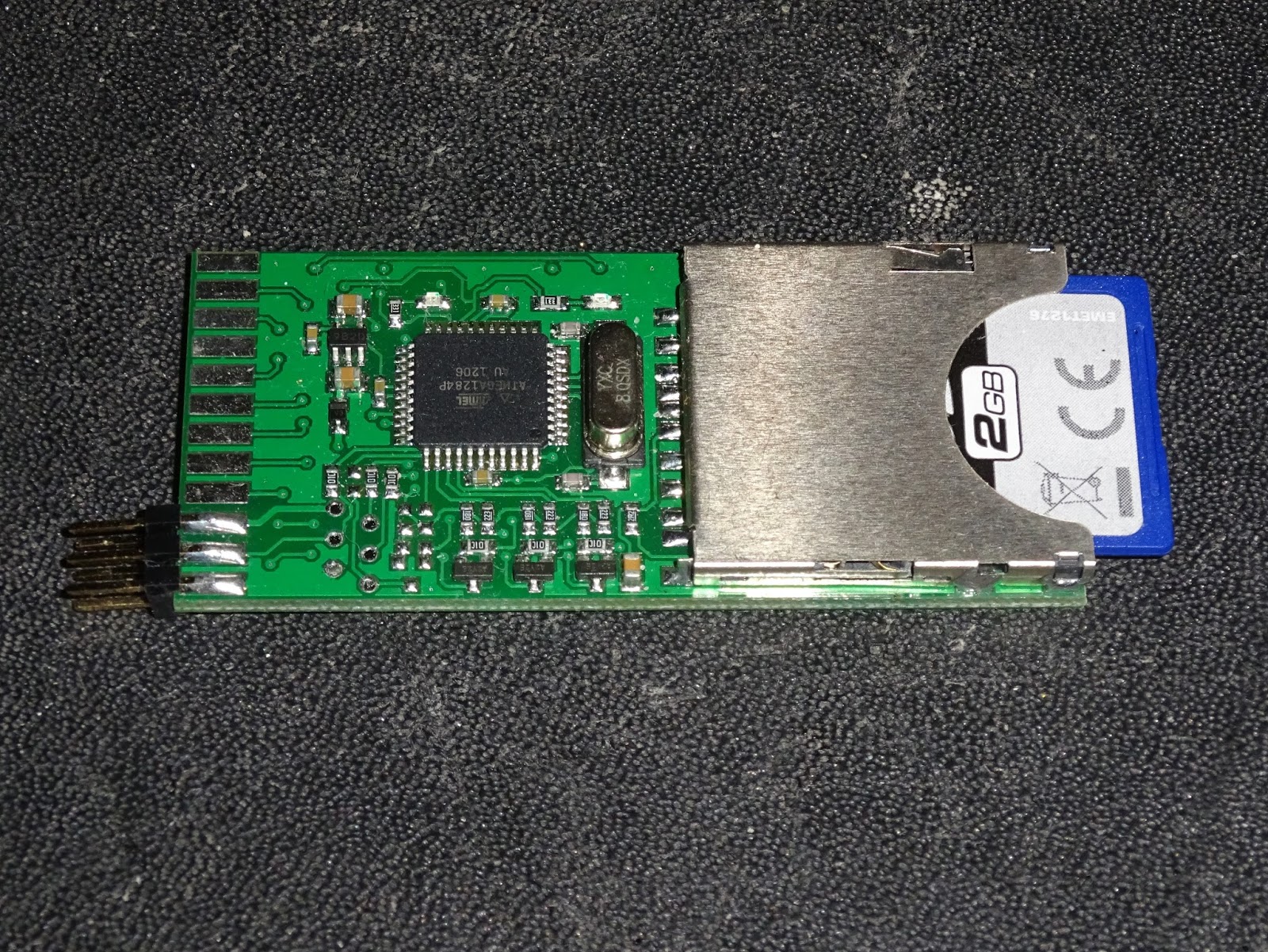
The internal SD2IEC boards (the SD2IEC Classic V1.0) are similar to those used inside the normal SD2IEC units, but without the buttons. There are additional contacts at the edge of the board to fit buttons and duplicates of the onboard LEDs.
The only pins needed for the IEC bus are 6 at one end, so I fitted a 6 pin 0.1" header, soldered to each side of the board. You could just solder the wires directly, but I thought this would be neater and would allow it to be removed easily if necessary.
There are various points at which the wires can be attached, I chose a set of vias just before the 6pin DIN socket. These were a bit tarnished, but with some desolder braid and extra flux they cleaned up nicely.
I've marked the connection points, these are relevant to this revision of the board, the VIC20-CR 250403 / 251040-01 Rev D. Always a good idea to check continuity to the socket to make sure you have the right pins.
I've tapped 5V and ground at nearby vias and attached five wires to these five vias.
On the end I've fitted a 6 pin connector suitable to fit the 6 pin header (Harwin M20), and plugged this into the SD2IEC board.
I was initially thinking of resting this between the DIN sockets and the VIC shielding, but in the end I've gone for attaching it to the lid of the VIC shield with foam pads. Making sure the contacts are clear of the metalwork.
Testing this, the lights flash reassuringly and the file browser appears. If I were planning to close the case up, I think I would look at changing the VIC20's power LED for a tricolour one, red for power on and then amber for disk access.
This one, however, runs mainly without a lid, with the prototype Penultimate Cartridge installed, so the onboard LEDs are fine. My bench is now a little tidier.

Update: an internal SD2IEC for a C64C.

Wednesday, 10 June 2015

PET microSD 8032-SK internal fitting guide

This is an old post, preserved for reference.
The products and services mentioned within are no longer available.

This post has been left for historic information. The PET microSD is no longer in production. The replacement SD2PET is available now, more information on the pre-order page.

Here is a bit more information on installing one of my new PET microSD Commodore PET disk drive replacements inside a Commodore 8032-SK or 8096-SK.
The normal PET miroSD has an edge connector soldered to the board, and plugs into the rear of a 4032 or an 8032 or similar.
The 8032-SK doesn't have edge connectors on the rear, it has IEEE-488 connectors.
Inside, it is actually the same board as the normal 8032, but it is rotated 90 degrees, and had cables connecting the user and IEEE-488 ports to the rear panel.
The 8032-SK version of the PET microSD does not have the edge connector soldered on
The kit includes the board, a power cable and a riser.
Temporarily remove the rear panel cable and the riser board can be installed where it used to connect.
There is then a special slot on the riser into which the pet microSD connects. The connections on this socket have been reversed for this purpose.
The pet microSD rests above the board, supported in the socket. Make sure it is not making contact with anything below, there should be a clear gap.
Power is taken from capacitor C11, the grey one in the photo above. The polarity is marked on the board and the capacitor. The black 0V rail should be clipped onto the lead near the edge of the board, and the red 5V lead to the other end, marked + on the board. If it doubt, check with a voltmeter.
The other end of the power cable connects to the pet microSD, again with black to the edge of the board, and red marked +. Here it a closer view, with a piece of white paper behind for clarity.
The original rear panel cable can then be reattached to allow other IEEE-488 devices to be attached to the pet as normal.
The edge connector on the top of the riser board is the now the same as the original edge connector, so connect the cable in the same orientation.
From the side, you should be able to see how all this fits together.
If you would like to order an 8032-SK kit or indeed a normal pet microSD kit, contact me.

2022 Update: I have since designed a much nicer SD drive for a PET. The SD2PET is available from  The Future Was 8 bit Note there is not a version which will fit the 8032-SK.

Monday, 8 June 2015

pet microSD - Commodore Pet SD card disk drive

This is an old post, preserved for reference.
The products and services mentioned within are no longer available.

This post has been left for historic information. The PET microSD is no longer in production. The replacement SD2PET is available now, more information on the pre-order page.

Update: The PET microSD is now available to buy, there are also some new versions for different models of PET.
This is a disk drive replacement for Commodore Pet range of computers, the 2001, 3000, 4000 and 8000 series.
Plug it into the IEEE-488 port of one of these machines and it will work as a standard Commodore disk drive, so all the standard BASIC commands such as LOAD "$",8 and SAVE "FILENAME",8 etc. will work. As will the BASIC 4.0 extensions such as DIRECTORY and DLOAD "MYFILE".
Unlike the petdisk clones I built previously, these boards are based on PetSD by Nils Eilers. This is a much better design that uses proper IEEE-488 bus drivers to connect to the PET, so should co-exist happily with real Commodore disk drives.
The original PetSD was based on SD2IEC, a very popular disk drive replacement for the Commodore 64 and other computers with the 6 pin din IEC connector. This has a very stable code base, with good support for file and access types, and D64 disk images etc. Nils has forked the SD2IEC code to produce NODISKEMU, and that is the firmware that is running on the PET microSD. It is compatible with the original petSD firmware as well, but the new code is recommended. This firmware is still under development, and can be updated as new versions are released by placing the update files on a microSD card - no programmers are required. There are various new products soon to be available in the world of pet disk drives. Dave Stevenson has a useful comparison matrix.
There are various connection options. The standard version will plug into the back of a 2001 / 3000 / 4000 / 8000 series pet using the IEEE-4888 edge connector. Power is supplied from the datasette drive connector.
Alternatively, power can be supplied by clipping into a reservoir capacitor inside the pet, with the cable fed out next to the connector.
This gives a slightly neater appearance, and frees up the rear datasette port.
The standard edge connector version with either power connector is £50.
The 8032-SK and 8096-SK do not have the edge connector at the rear, so there is a version for them which fits internally. Inside, it's the same board as the 8032, but the edge connector is not externally accessible, it has extension cables connecting the edge connectors to GPIB IEEE-488 connectors on the rear.
The pet microSD can be installed via a riser board which has an edge connector at the top to allow the original rear panel cable to plug in.
The 8032-SK internal mount version is £60.
For those with multiple Pets, there is a version that can be used for either 8032-SK internal mounting, or with a different riser card, on the standard pet edge connector.
The multi connector kit is £70, and comes with both risers and both types of power connector.
Finally, the 8296, 8296D and some early 8032's have a 24 pin header connector on the board. Pet microSD can be supplied with a similar header to allow internal mounting in one of those machines, although this is currently untested.
The jumper on the side can be removed to make the SD card read only. The 6 pin header on the side allows connection of an FTDI or similar serial cable. Currently this is used for debug, but there are some interesting future plans for that.
Please contact me if you would like to order one of these.

Update:
I've now written a pet microSD user guide.

Update 2:
The new batch of pet microSD boards, in blue, also include a datasette power connector with passthrough.

Update 3 :

There are now some new versions for different models of PET, including internal mount. That link has buy it now buttons.

2022 Update: I have since designed a much nicer SD drive for a PET. The SD2PET is available from  The Future Was 8 bit