Sunday 26 June 2022

Custom ROM sets for the Mini PET and PET ROM RAM

This question has come up a few times recently, so I thought I would go into more detail.

The Mini PET and PET ROM/RAM both uses a single large EPROM to replace many individual ROM chips in the original Commodore PET. But more than that, they contain several different sets of these replacement ROMs, to give a choice of BASIC to match the machine they are going into.


PET Memory Map

To start with, lets have a look at how the various PET models split up the 64K memory map of the 6502.

Address range
2001 (8K)
3016
4032
8032
0000-0FFF
8K RAM
16K RAM
32K RAM
32K RAM
1000-1FFF
2000-2FFF
-
3000-3FFF
-
4000-4FFF
-
-
5000-5FFF
-
-
6000-6FFF
-
-
7000-7FFF
-
-
8000-8FFF
1K Video RAM
1K Video RAM
1K Video RAM
2K Video RAM
9000-9FFF
-
4K Option ROM
4K Option ROM
4K Option ROM
A000-AFFF
-
4K Option ROM
4K Option ROM
4K Option ROM
B000-BFFF
-
4K Option ROM
4K BASIC ROM
4K BASIC ROM
C000-CFFF
2 x 2K ROM
4K ROM
4K BASIC ROM
4K BASIC ROM
D000-DFFF
2 x 2K ROM
4K ROM
4K BASIC ROM
4K BASIC ROM
E000-EFFF
2K ROM
2K ROM
2K EDIT ROM
2K EDIT ROM
F000-FFFF
2 x 2K ROM
4K ROM
4K KERNAL ROM
4K KERNAL ROM


The bits that aren't ROMs

Character ROM

OK, so it is a ROM, but it does not contain executable code, is not accessible to the processor, and does not appear in the memory map. It is wired directly into the video circuitry. This means it cannot be replaced from the 6502 socket with a PET ROM/RAM, and is a separate ROM chip on the Mini PET.

Video RAM

Video RAM is also a special case. It does appear in the memory map, but is still separate from the main RAM, and cannot be replaced by a PET ROM/RAM

IO Cutout

The 2K region from E800 to EFFF was not allocated to ROM and was used for memory mapped IO. Later machines reduced the cutout to E800-E8FF, allowing the remaining space to be used for extensions to the edit ROM.


BASIC Versions

There were several versions of BASIC, each of which will run on most of the machines in the PET range. There can be a bit of inconsistency with the numbering. This is my take on it.

BASIC 1  *** COMMODORE BASIC ***

This is the original version from the 2001 which has a few bugs. I don't generally include this in any ROM sets.

BASIC 1r *** COMMODORE BASIC ***

This is a patched version of BASIC 1 which fixes some of the bugs (but notably not the one that stops IEEE-488 disk drives being used). This is the version of BASIC 1 I use.

BASIC 2 ### COMMODORE BASIC ###

This is the second major version of BASIC, available as an upgrade to the 2001, and used on the 2001N and 30xx series. Sometimes referred to in older books as "new ROMs". It is also sometimes called BASIC 3, since it was used on the 30xx series of machines, and was followed by BASIC 4, but I stick to calling this BASIC 2.

BASIC 4 *** COMMODORE BASIC 4.0 ***

No confusion with numbering this one, it says 4.0 on the screen. There are however many different versions of it. The original release had a few bugs that were fixed by replacing one of the five chips. I don't include the buggy version in any ROM sets, and just stick to the fixed version. Frustratingly, even after ruling out that buggy version, there are several different flavours of BASIC 4 for different hardware, which confuses things a bit.

There is a more pronounced split between the regions of ROM in BASIC 4. B000-DFFF is BASIC, E000-E7FF (and in some cases also E900-EFFF) is the screen editor and F000-FFFF is the kernal (that is how it is spelled in all the Commodore documentation of the day). The changes were all within the editor ROM, and that would often be the only one of the system ROMs that was socketed. I will not go into too much detail here, maybe one day I will do a detailed breakdown of how BASIC 4 fits together - I did a lot of reverse engineering when producing the Mini PET ROMs)

  • BASIC 4 for non CRTC machines
  • BASIC 4 for 4032 (normal keyboard, link linking etc.)
  • BASIC 4 for 8032 (business keyboard, windowing etc.)
  • BASIC 4 regional differences (DIN etc.)

Machines

Now we have seen all the versions of BASIC, let's look at the machines they ran on.

PET 2001

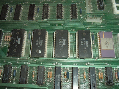
The 2001 had a total of 7 2K ROM chips, from C000 to FFFF, with a gap at E800-EFFF for the IO chips. BASIC 1 and BASIC 2 were available in 2K ROMs, either as 6540 ROMs on earlier machines or 2716 style on later boards. There was no space on the board for more than 8K of RAM or ROMs in the 9000-BFFF range. Options ROMs and even BASIC 4 could be added using expansion boards on the side edge connector, or plug in boards such as the PET ROM/RAM.

PET 2001N / 3008/3016/3032 etc.

The 2001N boards also had 7 ROM chips, but these were 4K each, and covered the complete range from 9000-FFFF (with the cut out at E800-EFFF). They initially came with BASIC 2, which left three sockets free for expansion ROMs from 9000-BFFF. They could be upgraded to BASIC 4 which used one of those for it's larger version of BASIC. These were the 9" 4008/4016/4032 machines. Not to be confused with the 12" monitor versions of the 4016/4032 I am just about to talk about.

PET 4016/4032 / CBM 8032/8096/8296

The various versions of the 40xx and 80xx boards had 7 ROM slots again. Often only the two options ROMs at 9000-9FFF and A000-AFFF and the editor ROM E000-EFFF (minus IO cutout) would be socketed. The others being tried and tested and unlikely to change. These machines had 6545 CRTC chips used to drive the display. This had to be initialised before it would display anything, so the correct editor ROM has to be used. It means that these machines cannot run earlier versions of BASIC as they do not initialise the CRTC at boot up.


ROM images

The PET ROM/RAM boards replace all of the ROM from 9000 to FFFF, leaving the full IO region E800-EFFF alone. This is almost 32K, so it makes sense to deal with this in 32K blocks.

Considering the simplest case of a single ROM set, the 32K ROM image is mapped into the upper 32K of the memory map, with the cutouts for video RAM and IO.

ROM Image Address range
PET Address range
Use
-
0000-0FFF
RAM
-
1000-1FFF
-
2000-2FFF
-
3000-3FFF
-
4000-4FFF
-
5000-5FFF
-
6000-6FFF
-
7000-7FFF
0000-0FFF
8000-8FFF
Video RAM
1000-1FFF
9000-9FFF
Option ROM
2000-2FFF
A000-AFFF
Option ROM
3000-3FFF
B000-BFFF
BASIC ROM
4000-4FFF
C000-CFFF
BASIC ROM
5000-5FFF
D000-DFFF
BASIC ROM
6000-6FFF
E000-EFFF
EDITOR ROM*
7000-7FFF
F000-FFFF
KERNAL ROM

* including IO cut out E800-E8FF or E800-EFFF

In this simple case, the 32K ROM image is built up so that it maps to the upper 32K of ROM. The regions in the ROM that would map to the video RAM and IO region are ignored, and I sometimes use those to note what is in the ROM image.


Next consider a two ROM set version. a 27C512 ROM will contain 64K, two 32K ROM images. The first set is as before 0000-7FFF, which is mapped into the PET memory map at 8000-FFFF (minus cut outs). The second set is in the EPROM from 8000-FFFF, and is mapped into the PET at 8000-FFFF.

And so on, a 27C010 can contain 4 images, 27C020 8 images, a 27C040 16 images and a 27C080 can contain 32 ROM images, which should be enough for anyone. 

In all cases, these are 32K blocks just stuck together.

ROM Address
Contents
00000-07FFF
ROM set 1
08000-0FFFF
ROM set 2
10000-17FFF
ROM set 3
etc.
etc.


Building ROM images

To build a ROM image, I suggest working on 32K chunks at a time, and then combining those later to create the final ROM image. This allows you to go back and make different "mix tape" ROM sets of all your favourite versions of BASIC. No? Just me then.

The individual ROM images can be found online, the best source being the wonderful zimmers site.

http://www.zimmers.net/anonftp/pub/cbm/firmware/computers/pet/index.html

Any space not used should be padded with 0xFF characters.

I'll only give a couple of examples here, as this post is already far too long and has no where near enough pictures in.

BASIC 2

ROM Image Address range
Contents
File
0000-0FFF
-
-
1000-1FFF
Option ROM
Various / Optional
2000-2FFF
Option ROM
Various / Optional
3000-3FFF
Option ROM
Various / Optional
4000-4FFF
BASIC 2 C000
901465-01
5000-5FFF
BASIC 2 D000
901465-02
6000-6FFF
BASIC 2 E000 (Normal)
901447-24
BASIC 2 E000 (Business)
901474-01
7000-7FFF
BASIC 2 F000
901465-03

There are a choice of the E000 ROMs for normal or business keyboards.

BASIC 4

ROM Image Address range
Contents
File
0000-0FFF
-
-
1000-1FFF
Option ROM
Various / Optional
2000-2FFF
Option ROM
Various / Optional
3000-3FFF
BASIC 4 B000
901465-23
4000-4FFF
BASIC 4 C000
901465-20
5000-5FFF
BASIC 4 D000
901465-21
6000-6FFF
Editor E000 (Non CRTC)
901447-29
Editor E000 (40 column normal 50Hz)
901498-01
Editor E000 (80 column business 60Hz)
901474-03
etc.
so many to choose from
7000-7FFF
KERNAL F000
901465-22

There are many editor ROMs to chose from, for different hardware, different refresh rates, different languages, different keyboards etc. There are also differences to the way the screen editor works, with the normal keyboard, 40 columns builds using line linking to allow mulitple screen lines per lines of code. The 80 column business keyboards were single line only, but supported windowing modes where areas of the screen could be fixed (c.f. the status line in Zork).

There are many versions of the editor ROMs on Zimmers, including a couple I patched for alternate keyboard types. Those are the ones with .ts.bin extensions (my attribution appears to have been lost in the mail).

Other images types

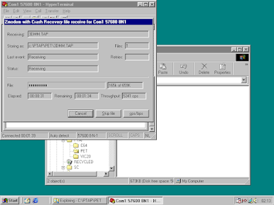
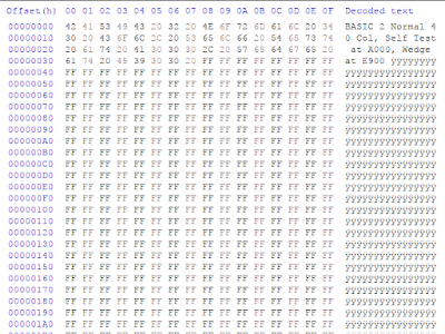
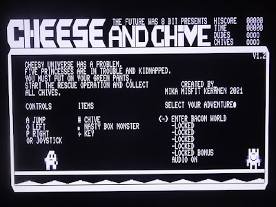
I think that is just about it. There are a few exceptions, you can put any code you want in there, you can run from 9000 through to FFFF with only the IO cutout. Put the usual NMI, IRQ and Reset vectors in the last six bytes and the rest is up to you. For example, see a previous post about running Cheese and Chive from ROM

http://blog.tynemouthsoftware.co.uk/2022/04/running-cheese-and-chive-from-rom-on-a-mini-pet.html


Advertisements

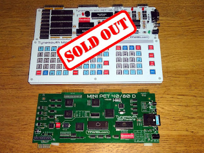
The Mini PET 40/80 kits are all sold out, but there are some Mini PET 40/80D boards still available from TFW8b NOW WITH £50 OFF (whilst stocks last) 

https://www.thefuturewas8bit.com/shop/tynemouth-products/minipet4080d.html


PET ROM RAM 

The PET ROM RAM is available from my SellMyRetro store (UK only, sorry)

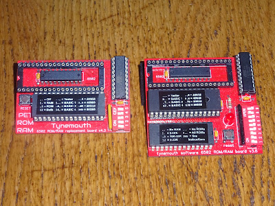
The smaller version on the left allows up to 8 ROM images to be select, and replaces either all or none of the ROMs and all or none of the RAM. Ideal for a fit and forget repair or upgrade.

https://www.sellmyretro.com/offer/details/62175

The larger version has up to 16 ROM images and has finer control of which regions of ROM and RAM are replaced.

https://www.sellmyretro.com/offer/details/62176

Patreon

You can support me via Patreon, and get access to advance previews of projects and behind the scenes updates. This now also includes access to my new Patreon only Discord server for even more regular updates.

https://www.patreon.com/tynemouthsoftware

Sunday 19 June 2022

Powering Commodore Datasette Drives

After last weeks post covering the modification of a Commodore datasette drive to create cassette masters, literally no one asked for more details on how the datasette drive was powered. So I thought that was a perfect excuse to go into considerably more detail on the subject.


The datasette was first introduced to go with the Commodore PET in 1977, and remained in use right through into the early 1990s. The original PET was almost entirely 5V. All the logic, ROM and RAM was 5V only. These were the days before the 4116 DRAM chips which need -5V and +12V as well. 

The exception to the 5V only statement is the datasette drive. It has a 5V supply for the internal logic, but there is a separate power connection for the motor, which should be supplied with 6V.

The arrangement is different from most cassette mechanisms. Normally there would be a permanent 6V supply for the motor, and a mechanical switch on the drive itself to turn the motor on or off, sometimes in series with a relay controlled switch on the computer end. The Commodore datasette relies on the host to use the sense line to detect when a key is pressed on the mechanism to turn the motor on or off. 

You will see some situations where these are driven from 5V, for example the old parallel port X1531 type transfer cables. These run the motor slowly, 5/6 of normal speed. This makes the tape move more slowly, so the data is written closer together on the tape. When played back at normal speed, it will actually be 20% fast. This is just about within the tolerance of the loading routine, so can speed up loading a bit, but it's not guaranteed, and wouldn't be recommended these days.

PET 2001

The PET's power supply was 9V DC unregulated, with several 7805 5V regulators, so 9V was available, and that was used to generate 6V for the motor.

There is quite a lot going on there. If you ignore the resistors and 2N3904 on the left, what you have is a 7.2V zener diode fed via a 1.5KΩ resistor, which gives a regulated 7.2V reference. The 10nF capacitor smooths the reference voltage, which is then buffered by the two transistors in a darlington arrangement. The output is a regulated supply of 7.2V, minus the two base voltage drops, 0.6V each, giving a 6V supply. 

Bringing back the 2N3904, when the Control signal is low, the 2N3904 is off, and does nothing, and the output voltage remains at 6V. When the control signal is high, the transistor is turned on and pulls the 7.2V reference voltage down, and in turn, the output transistors are turned off and there is no output.

That gives a simple switched 6V output. Control is high, motor is off. Control is low, motor is on.

VIC20 / C64 / C128 / TED

Over the years, that circuit was revised a few times, and I found quite a bit of variation from model to model and machine to machine. Different drive transistors, different zeners etc. The voltage is always "around 6V", but it varies from a little over 5V to almost 7V on some of the machines I have tested.

The final version in the TED machines like the C16 and plus/4 was much simplified.

This used a 7406 gate to replace the 2N3904 transistor, but still doing the same job of pulling down the reference voltage when the drive is not in use. Gone is the second buffer transistor, so more current is drawn from the zener reference, which had it's resistor value dropped to 470Ω. That does mean that when the motor is off, the 470Ω resistor is across the supply rails and wasting 20mA all the time.

Mini PET

When I designed the original Mini PET, I used the design from the TED machines shown above.


The two datasette drive circuits were drawing 40mA in total, with the rest of the board drawing less than 100mA, but it was nice and simple and a product of the last generation of Commodore optimisation. 

Mini PET 40/80

When it came to the Mini PET 40/80, there was an additional challenge to deal with, soft power on/off. I could have stuck with the same circuit, but the 40mA draw would have been present when the rest of the unit was switched off, not ideal. I could have added a separate transistor, probably a MOSFET, to switch the 9V rail before this circuit, but I was trying to simplify things.

I had used some new surface mount 6V regulators with on/off controls in the multi port duplicators I had made for TFW8b. Each drive had it's own switched and regulated supply, which worked quite nicely. I was able to use the sense input directly to switch them on or off, so no additional logic was required, not even a pullup resistor.


I would have like to use those, but they were only available in surface mount, or the sort of 5 pin TO220 packages that might be a problem for some kit builders as the leads are a bit close together. 


After looking around for quite a while for alternatives, I finally settled on the Micrel MIC2951. (Micrel is now owned by Microchip, but I haven't seen any Microchip branded as yet.)

This little 8 pin chips work in two modes. In the first mode, they are fixed 5V, 150mA regulators, with a shutdown input so they can be turned on or off via the soft power on controls.


The Mini PET uses less than 100mA, so 150mA should be fine. I used a second 5V regulator to supply the datasette port, more than enough for a datasette drive logic and powering an SD2PET.

The second mode allows the voltage to be set via a resistor divider (like an LM317 if you remember those). The shutdown signal is the same logic as the datasette control, low is on, high is off. A 74LS07 gate is used to pull the signal low when the motor should be on, the rest of the time, the 10KΩ resistor pulls it high and keeps the output turned off.


The value is set using the following equation, Vref is an internal 1.235V reference, and R2 is using the recommended value of 100KΩ. The nearest standard resistor value to give the output voltage we need is 390KΩ.

That gives an output voltage of around 6.05V. The value depends on the resistors which have a 5% tolerance (absolute worst case 5.59V-6.56V). The exact value is not important, as long as the voltage is within range and is constant during playback. Speed was expect to vary over the life of the drive due to belt stretching, so is accounted for in software (by timing the header tone at the start). The output is current limited to 150mA, to avoid motor burnout when rewinding or fast forward is left pressed and the end of the tape is reached.

That left the power section of the Mini PET 40/80 as four identical MIC2951 chips, and a pile of passive components.

Mini PET 40/80D

When it came to the Mini PET 40/80D, I was able to go for one of the surface mount 6V regulators with enable pins, so no need for the resistors, these were pre-set for 6V. The 5V regulator next to them is a plain fixed voltage always on type, as there was no need for soft power on with the 40/80D.

The on/off pin was now the inverse logic, so I needed to use 74LS06 dates to drive those, but it at least there were no zeners or set resistors.


Advertisements

The Mini PET 40/80D is still available from TFW8b (whilst stocks last)

https://www.thefuturewas8bit.com/shop/tynemouth-products/minipet4080d.html


This post is an combination of several posts from my Patreon. If you want advance previews of posts like this and behind the scenes progress on new projects, you can follow along and support me on Patreon (which now includes access to my new Discord server)

https://www.patreon.com/tynemouthsoftware


Sunday 12 June 2022

Creating Commodore Tapes - Adventures in Modern Recording

Publishing software on cassette in 2022 presents some unusual challenges. I am not sure how they did it back in the day, but it turns out traditional audio cassette duplication isn't really suitable.

When we were starting out with the Future Was 8 bit 499 range, we looked at various options, the most obvious seemed to be create a master tape and duplicate it. 


Creating master tapes from WAV files turned out to be a bit patchy, not a reliable result, and not a great candidate for a master to be duplicated further (and likely get worse). The master tapes created by saving the file from a real computer were always fine, those were written using good old Commodore Datasette drives.


I looked into a few different mechanisms to drive a datasette from a tap file. I tried adapting the arduino based board which can load files into a C64, which sort of worked, but I wasn't happy with the results, I wrote a program which ran on a PET, this was fine with plain files, but couldn't cope with fast loaders. Finally, I turned to an old piece of DOS software, ptap, which seemed to be the best option. This needed a 'proper' parallel port, i.e not a USB one, one using low level hardware wired direct to the pins.


It also need 'proper' DOS, not just a DOS shell in Windows, both for unrestricted access to the parallel printer port, and also for timing so it wasn't interrupted by system tasks and other programs. The easiest way to get that and a proper parallel port was to use an old laptop running DOS or Windows. 


Here I resurrected an old Toshiba Satellite 210CT (remember when laptops were grey?). The original hard drive was noisy and not in the best of health, so I started afresh with a 1GB compact flash card in an adapter to fit directly into the 44 pin connector for the old 2.5" IDE hard drive.


The external (proprietary) floppy drive wasn't working, but I managed to find an old bootable Windows 98 SE CD.


It was a long time since I had seen that screen, but was soon greeted with the good old logo.


And finally the welcome screen. Windows 98SE is my favourite choice for older machines, as it is pretty solid and functional, and since this laptop was "designed for Windows 95", by the time Windows 98SE came along, all the required drivers for the previous era of machines were included with the OS, so I didn't need to find any drivers for anything, it just worked.


I took out the CF card and used a USB CF card reader to copy over the ptap files and initial tape files. That is OK once, but I didn't want to have to keep taking the CF card in an out to copy new tape images on. This laptop is pre USB, and although Windows 98SE does support USB it is frustratingly difficult to get a USB storage driver to work. The floppy was out of commission anyway, but that would have been a faff to write to write files with a USB floppy then copy them back with the Toshiba external floppy. 


In the end, I went for a nice simple option of using RS232 serial file transfer. Windows 98 came with Hyper Terminal, which supports Zmodem file transfer.


At the modern PC end, Tera Term can send and receive a number of formats including Zmodem, so I pointed them at each other and pressed go.


It's not very fast or efficient, but in most cases I am transferring one or two tape images of a few hundred KB each, so it's no problem and saves messing around with anything else. 


Out of interest, I did take the above screenshot on the laptop and sent it back, it was a 1.4 MB BMP file which took about 4 minutes to transfer. 

With all the files transferred, time to fire up ptap.


Very nice. I am told the coloured flashing bars showing data only work on the oldest of video cards. Thank you Toshiba.

So that is the master tape generated, and it loads perfectly on all the machines I tried it on. You always get the best result using hardware designed for the purpose. The datasette is pretty much direct drive of the tape head. From the digital signal on the parallel port (or from a Commodore computer), all there is are a few 74LS14 inverters to buffer the signal and drive the write head. No audio filtering or automatic level controls to mess up the signal.


The trouble was, the audio duplicators are full of audio filters and automatic level controls etc. After various duplicators were tried and rejected, we gave up on the two stage approach of creating a master tape and then duplicating it. What we now do is create lots and lots and lots of master tapes. To enable this, I have built various buffering boards to feed multiple datasette drives from the one parallel port output.


I think there is a whole blog post to be written on powering and driving datasette drives, so expect that to follow shortly. 

That version added individual 6V regulator for each datasette's motor power. The latest also adds a second 5V regulator as it turns out TFW8b was running the boards from 12V instead of 9V as designed, so the single 5V regulator was getting a bit warm. (Each drive uses 25-50mA on the 5V rail and 100-200mA on the 6V motor.)

All TFW8b then needs is a small army of datasette drives, which luckily, they have.


And in no time at all* you have a box of perfectly duplicated master tapes.


* actually it takes an awful lot of time

Making a stand alone unit

I've built a few rigs for this, most of which have gone down to TFW8b to be used for mass tape duplication. The one I had left was quick lash up based on an old Mini PET PCB, built to quickly test a change to one of the VIC20 fast loaders.


That was a bit unwieldy, so to test out the 3D Monster Maze and Tut-Tut masters, I thought I would do a better job.

I decided the neatest solution would be to integrate the controller into a datasette case, and keep it all neat and tidy.

For that I need a datasette, and for a change, rather than the usual 1530 / C2N datasette designed for VIC20s and Commodore 64s, I went for a 1531 datasette, the dark themed version for the TED series of machines.


Here are four suitable candidates out of the 'broken' box. These were all a bit ropey and non-functional. 


This one had a squashed plug and a broken tape counter.


This one had a fantastic inline splice. I decided to start with that, and opened it up and rewrapped all the connections. One of the other drives had come with a cassette in, so I borrowed that and tried it out.


And it started loading....


It didn't finish though, it got to the end of the tape and failed. But that was good enough for me, perfectly normal for a tired datasette. The same reason why most of these drives fail. Loose belts and dirty heads. 


In many cases, you can get away with just using a head cleaner cassette - https://www.thefuturewas8bit.com/tapeclean.html

In this case, I could see the drive was a bit manky, so I stripped down the drive, cleaned the heads and fitted a new belt.


Belts for these drives are easily available, of course I get mine from TFW8b.com - https://www.thefuturewas8bit.com/shop/commodore/commodore-spares/c2nbelt.html 

I find the easiest way is to unscrew and lift up the PCB, and then there is just this plate to deal with. I under the screw on the top and loosen the screw on the side and rotate it up so the belt can slip out the slot in the side.


Whilst you have it open, also run some IPA over the play and record heads. and clean up all this beastly mud and oomska.


Do not touch the azimuth adjustment on the head. The only time I ever have to adjust the azimuth screw is when someone has previously fiddled with it and adjusted it away from correct alignment. It is almost always perfect as it is. Just forget about it, clean the heads and replace the belt and it will fix 99% of drives.

And there you go, first time I tried after that, Space Sweep loaded. A very colourful and action packed game it would appear, might have found it out more I had a C16 joystick to hand, but I didn't, so back to the drives.

I went through the other drives, and all were found to be functional. One the motor wasn't moving, but a quick turn by hand and it started and is still running fine. A new belt and a clean head and it loaded.


I like to label up the ones that have had new belts and a bit of a clean up.


But I also kept one as is, without cleaning the heads or replacing the belt. It worked well enough to load a tape. I keep these for testing master tapes on 'representative hardware', i.e. ones that haven't been cleaned up to serviced, just like the ones the people at home might be using.

I was left with the one with the mangled plug, I wasn't able to save it, one of the pins had broken off, so I cut it off and borrowed the end of the cable from the drive where it was twisted on.


This is not the approved way of testing things. Don't do this!


Again it worked well enough and actually loaded, so I was left with a drive that had a damaged plug on the end of it's lead that I had cut off. It also had a broken tape counter, and I was able to take one from a damaged 1530 drive.


Now onto the conversion process. The datasette drives need two power supplies. The first is a fixed 5V used for the logic and the opamp. I plan to power the drive from a 9V DC supply (the same used on the Minstrels, Mini PETs etc.). 

The datasettes use about 25mA on the 5V rail, rising to 50mA when recording, so I went for a simple TO92 regulator rated for 250mA. I wired that up with all the parts soldered directly to each other, and used heatshrink to separate the wires. Not exactly the neatest solution, but you haven't seen what I did for the motor yet, so appreciate this whilst you can.


The next one is a bit complicated. It should be a 6V supply, but only active when one of the keys are pressed. Some similar cassette mechanisms (e.g. the ZX Spectrum +2) have a leaf switch which is activated when a key is pressed, and that switches the negative connection to the motor.


You can see here on the right the Commodore drives also have a leaf switch, but these are only used as a logic input, so I wasn't sure if they were rated for the motor current. I expect they are, but I wanted to play it safe. Also, the switch is used as an input to the computer to tell a button is pressed. This is pulled up to 5V, and grounded when a key is pressed. I have used this input to control the shutdown pin of a regulator before, but the ones I was using have an active low output, so would be off when the button was pressed, so I had to use an inverter.


I didn't want to have to add an IC or a transistor to act as an inverter, so I went for the other 6V regulator circuit I had been using on the Mini PET.

This uses the 8 pin DIP package regulator, set to 6V using the two feedback resistors. I implemented that as very much a 'point of load' regulator. Soldered, as it was, directly to the top of the motor. These are rated for 250mA, and I have found they generally run cold even when the motor is running, and draws about 100mA. (my original plan had been to bolt 7805 and 7806 regulators to the metalwork somewhere, but it turned out neither were necessary).


All I needed to do then was to tap onto the 'sense' wire which is connected to the switch. I also added a pullup resistor to 5V, rather than relying on that happening somewhere inside the laptop.


I retained the original seven core screened cable, and attached two of the now unused wires to a short piece cut off the end of a 2.1mm DC jack extension lead. The rest of the wires attached to the 25 way D connector for the parallel port.


With the cover installed, it looked quite neat.


Less so inside the unit.


But it was starting to look tidier once it want back into the case.


Before I closed it up, I wanted to check it was all working, so I tried a few tapes and the motor spun when it was required to, and was able to fast forward and rewind.


Once I was happy the mechanism wasn't going to chew tapes, I tried a 3KHz test tape. I captured the digital output from the back of the drive.


It averaged 3.001KHz, that's probably a fluke, but it shows it's around the right speed, 2.98-3.02KHz is more than close enough.

Time to introduce it to the Windows 98 laptop. On reflection, I should have cut the cable shorter, but it's too late now.


Time to write a tape, so I grabbed a brand new C20 cassette - https://www.thefuturewas8bit.com/shop/media/c20.html 


I booted the laptop to DOS and ran PTAP.

When instructed, I pressed play and record and the LED came on. 


That all seemed to work, so over to the Mini PET to try and load it.


3D Monster Maze loaded first time, and I found the exit first time I played it, so that must be a good sign.


You may ask why I was loading from tape 2?

Where do you think I stole the MIC2951 regulator from? The lead time on those is currently a rolling six months, so I'd better get used to it (or swap it with the one from tape 2 which is more sensible).


It wasn't released when I started these posts, but the reason I was running the tapes was testing out my PET version of Tut-Tut.


Hey, I took a picture of a CRT and it wasn't totally awful!

That's running nicely on all the hardware I tested. This is the point where I specifically try to use tatty unmodified datasettes to try out the worst case someone might have at home when they try to load a tape.


Bonus!

When I was writing up these posts for Patreon, it occurred to me that I quite liked that laptop, and I should maybe see if I can find a similar model on ebay to fix some of the issues. 

And here it is, £30 of broken 90s laptop (half of which was shipping).

This was a 210CS, a lower model with a worse screen (the 210CDT has a nice TFT panel). It is also the CS not the CDS, so comes with a floppy drive, rather than a CD ROM and an external floppy drive in an external enclosure (the type where you can swap the floppy into the laptop, but you can't then use the CD externally).


The laptop has some video card issues, lines on the screen. I tried an external VGA monitor, and could switch between them using the FN keys, but the VGA output was no better. I'm not too bothered about that, I'm just putting that aside as a source of spares for the future. What I am interested in is the bits I can transfer to the other laptop.


I was hoping the floppy drive and battery would be in better condition than mine. As a bonus, I got a broken hard drive and a Sportster 28.8 modem. It's no wonder IBM got out of the hard drive game, if you have to put warnings like this on your drives, you are doing something wrong. People are going to pick it up, rattle it and say "oh yeah", and quite possible damage their drives in the process. 


The star of the show however is something I didn't expect, and never thought I would find. The exact proprietary 16MB memory upgrade module.


That's right, my Windows 98 laptop now has 32 whole megabytes of RAM!

The hard drive was not detected, and was making the usual clicking sounds you get from IBM drives like this and the 'deathstar' 3.5" versions. No real loss there, I'm happy using the CF card, and I have piles of old hard drives.

The floppy drive did the same as the previous one unfortunately. The ominous sound of a motor spinning freely, indicative of it no longer attached to anything. I had been hesitant to take the previous drive apart, as there looked to be lots of plastic clips that could easily snap, but I thought I would have a look at this new drive and see if it could be repaired.


And indeed, as unlikely as it may seem, this is an early enough 3.5" drive that it uses a belt driven spindle. And the belt is old and stretched and hanging loose, but at least not turned to black goo as they sometimes do.


I tried to replace it, but I didn't have a suitable belt. It needs to be flat profile, and the only one I had that would fit was square profile, so it rubs. It does spin and tries to seek, but all I get from Windows is "Device is not ready"


I'll keep looking for a suitable belt (found one on a US site, but shipping is complicated these days). I suspect if I were to look for another drive it would likely be in the same state, and it's a proprietary undocumented flat flex with combined power and data, so no easy path to a replacement. It would be useful to have a floppy drive available, so I will keep looking. 


No immediate plans for the PCMCIA Faxmodem. I thought it would be useless without the lead, but it turns out it has a neat pop out RJ11 connector. It's still pretty much useless these days unless anyone is running their own dial up server.


The battery is better than the one I had, this one charges and runs for several hours, so I'll keep using that one. But the clear winner is the memory module, it was worth it for that alone.


Advertisements

The TFW8b produced cassettes are available here:

3D Monster Maze - https://www.thefuturewas8bit.com/cas022.html 

Tut-Tut - https://www.thefuturewas8bit.com/cas024.html 

All the rest of the tapes and cartridges - https://www.thefuturewas8bit.com/shop/games.html

Digital downloaded are available form my itch page: https://tynemouth.itch.io/ 


This post is an combination of several posts from my Patreon. If you want advance previews of posts like this and behind the scenes progress on new projects, you can follow along and support me on Patreon:

https://www.patreon.com/tynemouthsoftware