
The top of my Commodore wish list was dominated by the final iteration of the PET / CBM machines, the 8296, the SFD-1001 single IEEE-488 disk drive, the 8250LP dual IEEE-488 disk drive and the 8296D (an 8296 with a built in 8250LP).

I was lucky enough to pick up an 8296D at a local auction a few months ago. I am hoping to get onto restoring that next. I also picked up an 8250LP in the same auction. Still holding out for an SFD-1001 and a plain 8296.

As part of testing the Mini PET 40/80D, I wanted to test the internal SD2MiniPET drive working with an external IEEE-488 drive, so I thought I would push the 8250LP up the queue and get that working to complete the testing.

Before even plugging it in, I wanted to check the mains filter inside the unit. There are various types across the range, from the notorious grim Rifa caps in the 8296, to the cigar shaped ones and IEC socket types in later CMB machines.
The 8250LP has the "filter in the IEC socket" type. These tend to be OK, but I have seen a couple that have gone bang in the past, so I will replace it later. It should be OK for now. (I remember I once said that about a BBC model B power supply where one of the Rifas went bang almost immediately.)

This is one heavy power supply, with matching linear regulators providing one 5V rail and two 12V rails.

The two bigs caps are 27000uF at 25V and 27000uF at 35V. I would have though economies of scale would have made it cheaper to use 27000uF 35V for both capacitors, but I guess the 25V ones were sufficiently cheaper that it worked out better that way. If Commodore could have saved a couple of bucks, I am sure they would have.

I disconnected the power to the boards and measured the rails off load. All the rails measured correctly, so I reconnected the boards and powered on again.
On to the main board. Big, isn't it?
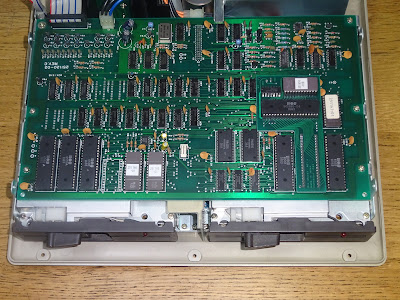
Two 6502s, four ROM chips (2x8K, 2K and 1K), four sets of RAM (4K of SRAM, and 256 bytes each in two 6532s and one 6530).
The 6530 is on a daughter board. This is an unusual arrangement. The 6530 RRIOT is ROM, RAM, IO and Timer. However this adapter disables the ROM part of the 6530 and maps in a separate EPROM to the same address space.
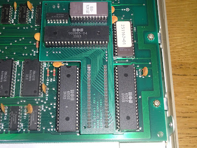
I understand this was done to use up the stock of RRIOTs with the ROM for previous model disk drives. This one has a 901885-04, which contains firmware for DOS 2.7 with Micropolis disk drives, as used in the 8050 and 8250.
I presume they planned to go for a custom 6530 once these were depleted, but I don't think they ever got there. The date code on that 6530 is in the same range as the rest of the chips, so they must have been making new ones with the old code in?
I suppose this was using up old stock, but again, if they didn't need the ROM part, it would appear to have been cheaper if they had used another 6532 (RIOT, no ROM, just RAM, IO and Timer), of which there are already two on the BOM?

To help deal with the complexities of the dual processor system, the drive uses its LEDs to show diagnostic information. It has three LEDs it can control, one in each drive, and a central tri-colour LED (although it is wired from a single output which is inverted to drive the second LED, so it will either be red or green, never off or orange).

That is wired to the case, so for testing, I plugged in one of my test LEDs from my USB keyboard days.

When powered up, the LEDs flashed twice, a delay, then twice, then the delay etc. This indicates a problem with ROM E000-EFFF, the left hand of these two 8K EPROMs.
This is a rather unusual 2564, which none of my EPROM programmers can read. It is sort of compatible with the 24 pin 2364 with four extra pins with aren't much use, one is a duplicate of the VCC pin, and one is VPP for programming.

Since it was 2364 compatible, I was able use a 2364 adapter to replace the faulty ROM.
With that installed, I still got the two blink error code. I checked again, and yes, for this drive that means a ROM fault in that address range.

I tried an alternative method of replacing the ROM, using a ROM/RAM board to replace all the ROM from E000-FFFF. This also did not work, two flashes again.
I couldn't replace the RAM using the ROM/RAM board as I wasn't entirely sure of the memory map - it's a bit complicated because the two processors have a block of shared memory which is mapped at different addresses on both processors.
Thinking about what is going on here, the processor is reading through the ROM to do a checksum, and it is reporting that it is wrong. We know by replacing the ROM that it is correct, so then either there is something conflicting on the bus at that address which is causing it to be read incorrectly, or the RAM it is using to calculate the checksum could be bad. Since bus contention on a multiprocessor, multi ROM, multi RAM system like this would be a nightmare, I tried the RAM first.
It is most likely to be using the zero page RAM, and that is in one of the 6532 chips. I tried replacing the 6532 with was mapped as zero page RAM and that did it. One solid green light.

I replaced the faulty chip with the new logo (stamped Korea) with the one with the old logo (marked Hong Kong), which is two weeks younger (but still nearly 40 years old).

Time to plug the drive into a board and see what it does.

Oh, that's good. I was very pleased to see that.
I tried to read a disk created on an 8250, but it didn't read it, the door lock didn't seem very solid, but it appeared to be trying. I tried a formatting a blank disk, but that also failed.

Ah, but this is a dual drive. I wonder if drive 1 does any better?
That felt a lot more solid when I latched the disk in, and formatted correctly.

I tried some tests, but with drive 0 failing, I couldn't get through the full test, but drive 1 appeared to be working well.
Removing the main PCB reveals the two drive units. Here I found the bug.

Removing that didn't seem to fix the problem, so I removed the next layer of covers and found a second bug.

Hmm that doesn't look right.
Not sure what that is about, but I am sure the PM will deny he ever had a filofax, but even if he did, it was within the rules......

Reminds me of the Nintendo Wii I was asked to repair last month by my Sister.

Apparently one of my nephews was trying to get it to play a jigsaw.

Back to the 8250LP. That bit of old disk label wouldn't have helped things, but I could see the problem was actually a bit of plastic that was snapped. It is used to push down the clamp onto the spindle and engage the disk, so it is clear why it wasn't working.

It was actually split, but both parts were round enough to hold onto the shaft.

The one on drive 1 was only partly split, but still holding on.

I glued drive 0's latch back together, and put some glue over the split on drive 1. I also cable tied the bottom of both drives to hold them together (I stole that trick from a Nightfall Crew post).

Let glue dry.
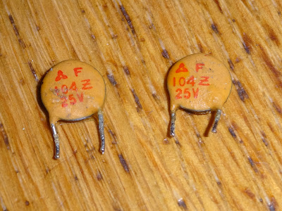
Before putting everything together, I thought I had better check the drive PCBs, there seems to be a common issue of one of the capacitors leaking.
Oh dear, that has happened, but it doesn't look too bad on drive 0.

Oh dear, drive 1 (the one that worked) is worse.

I removed the flywheel to check underneath and it's spread a bit further around there.

I cleaned off what I could and attacked the soldermask with a fibreglass pen to see what the copper was like below.

The screws in holding those boards in were infeasibly tight. I managed to get the nearest one out on both drives, but the other three wouldn't budge. If I had of used any force, it seemed like the screws would have rounded off or snapped, so I decided to work with it in situ.
I was able to desolder the caps from above and pull them out.

I removed the 100nF disc capacitor next to them as well to make it easier to check the PCB out.
Drive 0's board cleaned up quite well.

Drive 1 was a bit more of a horror show, but there was enough remaining copper to go around.

I couldn't find a suitable replacement capacitor in stock anywhere, so I went for a Nichicon cap with higher voltage rating and a slightly taller case.

I wasn't bothered about the extra height as I couldn't remove the PCB anyway, so I installed the replacement capacitors on top of the board. Not the neatest, but it will do the job.

I tinned the exposed copper, and to further protected it, added some clear varnish.

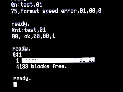
Putting that back together to test it out. Both drives seemed to be latching properly, and both read disks. However, when I tried the format test, it again failed the speed test.
Using the speed test part of the 8296D diagnostics programs, it showed drive 0 speed was 6mS out.

The speed adjustment screw is on the bottom of the drive PCB (who's idea was that?), so it was a little precarious adjusting that.

From there I was able to adjust the speed and got the live display on the screen down to 0ms. After that, I retried formatting and all was well.

The performance test did a lot of reading and writing and finally passed.

I did a fair bit of testing, moving files around from disk to disk, and from SD2PET to disk, using CBM Command, which works rather nicely in 80 column mode (but unfortunately doesn't handle .d80 or .d82 disk images).

The final task before reassembling was to remove the mains filter. I replaced it with a standard IEC socket (is it a socket, it has pins?).

The original version (with the built in filter) has the wires soldered to pins coming out the top.

Wire colours follow the US standard of white as neutral, black as hot. Never understood black being the live wire, but I guess we had dull brown as live and the bright blue was neutral. Before that we had red as live and black as neutral, which makes more sense, but is probably a bad idea anywhere there is DC inside the case.

The replacement had tabs on, so I used crimp connectors to attach that. The same style already used on the earth screws and capacitor screws terminals.

That mounted with the same screws, so it should look no different from outside the case.

Underneath the filter, you can see the schematic with all the caps that could let out their magic smoke at any moment.

With that done, it was time to clean up all the plastics, and put it all back together.

The serial number is on the base, so I guess this was the 1641st 8250LP drive?

That cleaned up quite nicely.

The chassis slides and then screws into that.

The new IEC socket fits fine.

The drives each have a bundle of digital control / power wires and a separate analogue cable.

The cables from both drives plug into a small board that sits between them.

16 mod wires on the back, quite a lot for a "production" board?

That all goes together neatly with the wires tucked away.

With all of that reinstalled, time for the main PCB.

That only has four mod wires. You can see the pin header than connects to the vertical board below.

All back in place, so finally, the lid.

I like the dealer sticker on the front of the drive, Currie & Maughan in Gateshead, about 10 miles away from where I am, here in Tynemouth.

The same dealer stickers that was on my first PET 4032. It's not on that PET anymore as it's edges were too damaged.

The 8250LP (low profile) is quite a lump, lower and lighter than the 8250, but still quite a size (SD2PET for comparison).

It does make quite a handy stand for your Mini PET 40/80 though.
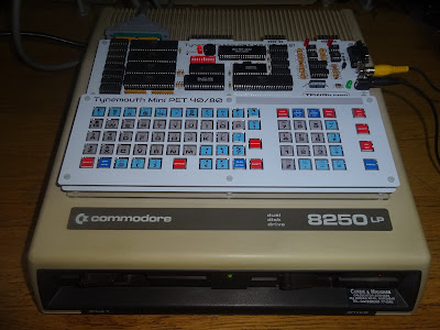
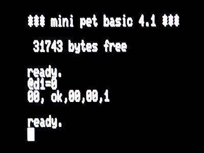
I've been testing that quite a bit and it's running very nicely. You can even do things like this, @d1=0 copies the disk in drive 0 to drive 1, all in single command, and all done inside the drive.
Not too bad a repair, one bad IC, two leaky caps, two bits of broken plastic and a note from Boris's secretary.

The 100nF caps were innocent victims of the 33uF caps, and the mains filter wasn't faulty (yet).
Well, that was quite a post, probably should have been in weekly instalments, free binder with part two.
Advertisements
The Mini PET 40/80D pre-assembled drop in replacement PET boards are still available from The Future Was 8 bit.
It doesn't look like it is going to be possible to get another batch of these made any time soon, so this is yet another product you need to snap up now if you want one.
https://www.thefuturewas8bit.com/shop/tynemouth-products/minipet4080d.html

https://www.patreon.com/tynemouthsoftware
