Sunday 27 August 2023

Inexplicable Autofire Explained (sort of)

Today we have a Patreon post during the development stages of the Penultimate Cartridge. Trying to fix a problem with a couple of the games.


During testing of the Penultimate+2 Cartridge, many games have been played and tested by many people.

There are too many in the cartridge at the moment, we have a few more to add, so we need to remove some, and are trying to weed out the weakest of the titles currently in there.

Some are down for removal because they aren't very good, or because they are too similar to another game etc.

Some are marked up because they have issues. We could just take those as a given and remove them, but I would like to know what is going on.

One of the games that is a problem is Bandits. Ever since I was asked to add it, I have been reporting that it seems to be stuck in autofire.

This wasn't always seen by the other testers, some of which reported no problem and it played normally.

This has been through various rounds of testing and various theories. One being related to another oddity seen previously, a couple of games with "please stop tape" messages.

In the post on those conversions I mentioned that seemed redundant as the Commodore Datasette had motor control, but it turns out that was due to the way the joystick is read.

OK, here goes.

Ports A and B on the user port VIA chip has various things connected to them:

  • PA0    Serial CLK in
  • PA1    Serial DAT in
  • PA2    Joystick 0 (up)
  • PA3    Joystick 1 (down)
  • PA4    Joystick 2 (left)
  • PA5    Joystick Fire
  • PA6    Cassette Sense
  • PA7    Serial ATN out
  • PB7    Joystick 3 (right)

It may seem odd that three of the directions and fire are on the one port, and the forth direction is on a different port. Indeed it is. Would have made more sense if they were all on the same port, or at least the four directions on one port and fire on the other.

Who knows why they did that. May have been to do with routing the board or a last minute shuffle of pins? But I am sure it has been annoying game developers for 40 years.

The problem is when the game designers for whatever reason expect the values for the other signals to be at some fixed value (as they are on their system), but they are read differently on your system. It should be possible to mask out those bits, but maybe they didn't think that was necessary, or wanted to save space or improve response times.

In simple terms, in BASIC do a PEEK and check the value returned. If fire is not pressed, it read 126, and 94, if fire is pressed. But when the datasette sense line is active (i.e. play is pressed), the values read will be 64 less that those before, so 62 or 30. If you code is checking for 94, it will never detect fire being pressed if the play button is also still pressed.

Also in that 8 bit port are the inputs for the IEC serial CLK and DAT signals. Those can also affect the value read.

If you do a LOAD "$",8 and then repeat the PEEK, you now get 127 instead of 126. Again, if you mask out the bits you don't care about you should be fine, but if you are checking absolute values, it will fail.

As seen in a previous post on IEC fault finding (http://blog.tynemouthsoftware.co.uk/2023/06/diagnosing-iec-bus-faults-on-vic20-c64.html), writing to the output pins affects the values read on the input pins, so again you can break the simple value comparisons.

Testing this theory, Bandits with no IEC device connected works fine. Bandits with an IEC device autofires. If you reset the IEC device, the autofire stops.

I have tried with a datasette, and that made no difference, so it is only the IEC lines

I think we have the culprit. But what is going on?

I went through reverse engineering the process, basically it rotates the byte that is read around to make it easier to test the lower bits, and somewhere along the line, the two versions diverge. 

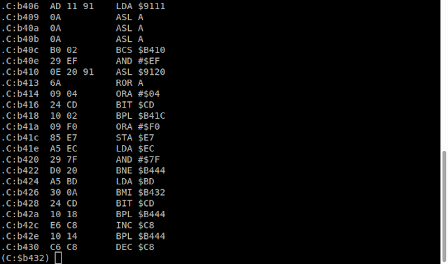
However, I was not able to pinpoint 1) where the test fails, or 2) anything that could be changed to fixed that.


The hardware level

To test the theory, I setup the scope to monitor the CLK and DAT lines, with a trigger on reset.

Booting up the VIC20 with no cartridge installed. With or without an IEC device connected, at reset (blue), the clock (yellow) and data (green) lines both are pulled low and then released and stay high unless a device on the bus wants to talk.

Booting up the VIC20 with the Bandits cartridge and no IEC device connected is different, but still returns to normal.

Booting up Bandits with an IEC device connected, however, is a problem.

As you can see, clock does not get raised. It stays low, and affects the value read on that port, causing the autofire. The VIC is not pulling CLK low, it is the external IEC device.

If, you reset the IEC device (which was pulling CLK low), it is released and things return to normal. The firing stops.

So let's unpack that.

What is happening is even though the VIC has released CLK and DAT, the external IEC device is still holding down CLK. But why doesn't that happen in normal circumstances?

Well, a series of events happen which clear the bus. This is not happening with Bandits as it bypasses all the standard initialisation stuff and does that it's own way (which doesn't clear the bus properly).

How to fix it?

I have tired various ways, and not found one I like.

The first I tried was to make sure this was actually the problem.

The code is full, so no easy easy way to add anything to the ROM.

I modified the code and replaced the LDA $9111 instruction which reads the port with JSR $2020 (why 2020? well, JSR is opcode 20, so the changed bytes were 20 20 20, and that appeals to my sense of balance)

RAM at 2000 onwards was not being cleared, so I preloaded that with some code:

LDA $9111

ORA #$03

RTS

All that does is read the port, OR the value with 3, which sets bits 0 and 1 high, acting as if both CLK and DAT were high, as they should be. It then does an RTS, and goes back to the original code.

I tried that, and it worked.

I don't plan to use this solution as 1) it affects the timing, and 2) would need a different change for each game (did I mention there were two versions of Bandits, PAL and NTSC, and also the same with Final Orbit, and possibly some other games?).

So, plan B.

I added some code to the Penultimate Cartridge launcher that would do the proper bus initialisation before starting the cartridge, so that it should already be set. However, that didn't work. It seems the way the port is being setup in Bandits is deliberately antagonising the IEC port and failing.

However, oddly, it did fix the problem on Final Orbit, so I have left that fix in place for that game, but I don't understand why Bandits isn't?

Comparing them, they both use loops to write a series of values to 90xx, 91xx and 92xx (the VIC and the two VIA chips).

They are different though, Final Orbit writes 01 to 9111 (port A), Bandits writes 07, although that should have no effect as those pins are inputs.

I have tried changing them and that didn't fix it.

Just as I was writing this up, I remembered about the other address for port A, 911F, and sure enough Final Orbit writes 88, and bandits 80.

Again, changing those made no difference.

It writes them in reverse, from 911F down to 9111, so 911F gets written first, then 9113 (which is the data direction register), then 9111.

So those pins are briefly used as outputs, but set low, so it shouldn't be a problem.

One more thing.....

Another thing I noticed is that maybe there is a bug in the code for Bandits. Shouldn't that be LDX #$0C at $A7Ef ? not LDY?

X is set earlier, but Y isn't used, and X is used as the offset by the LDA and STA instructions. Similar code in Final Orbit uses LDX (and the offsets are slightly different)

I did try changing that, but it still autofires, but now the graphics are messed up.

This one has me stumped. I've spent a bit too long on it now, need to get on with some other stuff and will maybe look at it again later.


I didn't get around to looking at this again, so the versions of Bandits on the release cartridge still has the auto fire issue. If anyone has any ideas how this can be fixed, please let me know.


Advertisements

Penultimate +2 Cartridge

The Penultimate +2 Cartridge, containing Key-Quest for PAL and NTSC, and many other games in stock at The Future Was 8 bit:

More info in a previous post:

http://blog.tynemouthsoftware.co.uk/2023/06/penultimate-plus-2-cartridge.html

See also a great video from Robin, 8 bit show and tell:


Patreon

You can support me via Patreon, and get access to advance previews of posts like this and behind the scenes updates. These are often in more detail than I can fit in here. This also includes access to my Patreon only Discord server for even more regular updates.

https://www.patreon.com/tynemouthsoftware

Sunday 20 August 2023

ZX Spectrum Issue 2 Future Proofing

I was expecting this to be a repair, an issue two ZX Spectrum that the owner bought on ebay with the ominous status of "working when last used, but no longer able to be tested". That normally means guaranteed broken, possibly raided for parts.

Rather surprisingly, when the owner tried it, it worked.

Obviously, this is an issue 2 Spectrum, so the screen is either going to be greeny-yellow or bluey-yellow, but that can be fixed.

The Spectrum was sent to me for some further testing, and selected preventative maintenance.

Inside, it looks clean and not messed around with. There are various mods, but I think those are all factory changes.

The "mandatory" mod to (try to) improve the switching power supply circuitry. The design changed with every revision, and it was always pretty ropey.

The usual "transistor on top of the Z80" mod which limits the IO decoding to "A0 is low" like the ZX80 and ZX81, rather than all addresses as the Spectrum originally did. This transistor was added to the PCB on later revisions of the board.

Also seen there is the 1K pullup on the clock line, and not shown, some further component substitutions on the left of the board. 

More about these mods - http://blog.tynemouthsoftware.co.uk/2017/01/zx-spectrum-issue-2-testing-with-divmmc.html

And finally this one is a bit unusual. Not seen it implemented this way before.

The upper 32K bank of RAM is provided by 8 64K RAM chips, only half of which is used. These chips were rejects with faults in one half or the other, and marked by the manufacturer as 32K chips. They came in two types, one with the bottom half usable, and one with the top half usable.

Jumper links were used to select which half to use, so all chips had to be the low or high type.

This is unusual as neither link has not been fitted, and instead a leg of one of the 74LS157s has been lifted and wired to 5V, and on the back of the board, two pins are solder blobbed to send an address line to that pin instead of 0V or 5V from the jumper.

The 64K chips have addressing as 8x8, 8 rows are latched, then 8 columns, giving a 16 bit address for 64K. Two 74LS157s are used to switch between A0-A7 and A8-A14 plus a dummy A15, which is hard wired by a jumper link either high or low depending on which half of the chips is good.

This was designed for Texas Instruments TMS4532 chips, which appear to be TMS4164 chips where one half has failed testing. (-L3 for lower half, -L4 for upper half).

This board has OKI chips, which has the dummy line at A7 rather than A15 (or it may be the other way around, my head hurts already).

It seems to have been a factory 48K board, so I guess they were using these with the extra mod on some of the later issue 2 boards.

Issue 3 and later boards had an extra jumper for this option to allow these OKI chips to be used as well as the Texas Instruments ones, and this modification appears to be the same as selecting the OKI jumper on later boards.

7805 Replacement

Now for the first change.

The standard Spectrum has a 7805 5V regulator. This is good, solid, reliable linear regulator, they rarely fail, and when they do, it is usually a no output situation.

The are, however, very inefficient. Given a 1A load and a 9V supply, 5W (1A x 5V) is used by the load, and 4W (9v-5v x 1A) is burned up as heat, hence the big heatsink.

Modern switching regulators can be over 90% efficient, so waste less energy as heat, so it is a worthwhile replacement to reduce the amount of heat in the tight case.

Later Spectrums had the regulator at the back of the board, so vertical switching regulators could be fitted, but the issue 2 has the regulator lower down in the case.

You can fit vertical ones on their side, with some header pins or wire links, but I like to use the right angled ones, such as this RS K7805-2000R3L, which is rated up to 2A, more than enough for the Spectrum and add ons.

https://uk.rs-online.com/web/p/switching-regulators/1934043

Capacitor Replacement ?

Next, the thorny question of capacitors. There seems to be a modern obsession that "all capacitors should be replaced", and I don't agree with that. There are situations where that is the case, like cheap modern electronics, and particular things from the 2000s where there were lots of bad capacitors around, or wax and paper type capacitors from the 1950s and earlier found in valve equipment etc.

These ones from the 1980s tend to still be good, and quite honestly may be better than the modern ones they would be replaced with. Makes me sad to see people cutting out perfectly good 40 year old Nichicon caps and replacing then with random ebay tat that probably won't last 4 years never mind 40.

I asked in the well curated echo chambers of my Twitter and Discord, and almost everyone agreed with me that they should not be replaced unless they are actually bad.

I did due diligence and tested several of them (lifting on leg so they can be tested out of circuit. They all passed. 

That is a 100uF capacitor. The original specification would have been -20/+80%, so it is well within range.

I compared against a few modern capacitors I would have used to replace them, and the values were similar, other than the capacitance being lower on the modern ones.

I don't think the value is particularly important. The basic range of capacitors available at the time were limited to 10, 22 and 47 with multipliers. So the designer would have looked at what they needed for the reservoir capacitors and decided 47uF was too low and 220uF was unnecessary and so went for 100uF.

The only one that was a little out of range was a 1uF capacitor in the reset circuit.

Seemed worthwhile to replace that and also the other 1uF capacitor, C46, as that was a critical part of the -5V circuit.

I tried a few modern ones, and they were generally worse, lower capacitance and higher ESR.

I decided to go for 1uF ceramic bead capacitors, which looked quite good, and I think they should be fine for that application.

The two 1uF capacitors are either side of the keyboard connector (where C46 is marked with the incorrect polarity, not that it is a problem with non-polarised ceramic caps). I raised the legs a little, as there were various traces below.

Transistor Replacement

Also in the power supply circuitry I replaced TR4 and TR5, as these are common points of failure in all Spectrums.

The ZTX650 was replaced with a ZTX651 which is the same, just with a higher voltage rating.

There was a BC308 fitted for TR5, which is a bit lower power than the ZTX213 it is meant to be. (Possibly a later repair, hence the power supply mod?)

I replaced with a ZTX751, which is both higher power and higher voltage rated.

Colour adjustment

To get rid of the yellow screen you need to tweak the two variable resistors. The official recommendation involves setting them to get a particular voltages (the inverse of each other).

I prefer to use the technique of tweaking each pot in turn to give the sharpest signal on the scope. - http://blog.tynemouthsoftware.co.uk/2017/11/zx-spectrum-issue-2-colour-adjustment.html

It starts of quite fuzzy. The sharper that line is, the whiter the picture is. Issue 3 and later boards do this automatically, there are no pots to adjust.

As you tweak them, the line gets sharper and less yellow / blue.

And that is about as good as I can get it.

Composite video mod

The last step was the composite mod. I have tried various options on issue 2 boards, and tried some of them again here.

The simple 100uF capacitor version works, but not very well.

I went back to my normal way of adding a TFW8b composite video buffer board.

Does the job nicely,

That is all the modifications complete.

ULA

One further thing I would like to look at would be the ULA. Like most Spectrums, the ULA runs hot, and will over time cook itself and fail.

I normally recommend getting a replacement, such as the vLA82, and preserving the ULA in a working state (rather than waiting for it to fail and then installing a replacement anyway)

In the Spectrum+ case, there is enough height to install a heatsink on the ULA to help a bit. There is not room in the rubber key case.

Some people desolder the ULA socket and solder the ULA directly to the board, so that there is space for a heatsink. I am not really a fan of that, it risks damaging the board, and will need to be redone when the ULA eventually fails.

In this case, the owner does not plan to use it heavily, and wants to keep it original, so the fact the ULA runs hot is accepted.

I did some soak testing to make sure everything was running well, but made sure to do that with the case open and a heatsink on top.

Faceplate

All that's left is a cosmetic fix.

The membrane it not original, and has been replaced in the past, made by a company called Tesla (not that one).

In order to do that, the faceplate would have been removed and replaced, if it had not already fallen off and been stuck back on several times already.

As you can see, lots of residue of past applications of glue and double sided tape.

You can get replacement faceplates, but the owner wanted to keep this one original, and it's not in that bad condition, so time for the slow process of cleaning all that off.

I use an old credit card or plastic business card, and some label remover spray. Don't use pointy metal things as they can damage the metal faceplate.

All clean, time for some new tape. I put that on the Spectrum first. Seems easier that way.

And there we go. There is still some glue residue on the faceplate, but it is a bit risky trying to clean that as it can take the paint off.

Testing

Testing all went well, no problems.

Of course, I am using a TFW8b divMMC future to load the games.

It's a hard job having to play all these games, but I just have to force myself to do it.

All done and ready to go back to the owner.

-------------

I wasn't going to write this post up, didn't think I had much to say......

Didn't even get on to the hFE testing on the transistors.

Or sorting out my capacitor collection to try to find more capacitors to compare against.


Advertisements

Minstrel 2 and 3 (ZX80 and ZX81 compatible)

There are Minstrel 2 and 3 PCB, full kits and build versions available from my SellMyRetro store.

https://www.sellmyretro.com/store/tynemouth-software

Minstrel 4D (Jupiter Ace compatible)

Minstrel 4D kits are currently on special discount at The Future Was 8 bit, in DIY kit and built and tested versions.

https://tfw8b.com/product/minstrel-4d-turbo-jupiter-ace-compatible-computer-kit/

DivMMC Future

The DivMMC Future is available from The Future Was 8 bit

https://www.thefuturewas8bit.com/shop/sinclair/divmmcfuture.html

Patreon

You can support me via Patreon, and get access to advance previews of posts like this and behind the scenes updates. These are often in more detail than I can fit in here. This also includes access to my Patreon only Discord server for even more regular updates.

https://www.patreon.com/tynemouthsoftware