Sunday 30 December 2018

Sega Master System II Composite Video Mod

This is an old post, preserved for reference.
The products and services mentioned within are no longer available.

In a recent video, ChinnyVision reviewed the Sega Master System, and was very scathing about the Sega Master System II.
The main reason (other that the 90s rounded styling), is the only video output on the SMS II is RF.
The original Sega Master System with it's 80s angular design not only looked better.
But had an RGB output connector.
All that is required to get a good picture out of these is and RGB SCART cable (as ever, I just got one from Retro Computer Shack as their stuff always seems to work).
So is there anything that can be done for the SMS II?
Under the rusty shield, is quite a small board (SMS Portable anyone?)
Good to see a real Zilog Z80 in the top right.
In the middle, is the same video output chip as the SMS, so if you don't mind hacking up the case a bit, you could install a DIN video output socket wired the same as the SMS.
However, an easier option to get an improvement over the RF output is to remove the RF modulator and install a composite video output.
Although that's easier said than done as the tabs on the modulator were folded over before soldering..
That leaves space to fit the 'Deluxe Composite Video Mod' from The Future Was 8 bit.
I've put the board back in the case to align the socket with the hole used by the RF modulator.
That should line up nicely to avoid any modifications to the case. The four pole 3.5mm jack is connected to three phono plugs, two audio (wired in parallel) and one composite video, so that's all in the one connection fitting neatly in the existing hole.
With that fixed in place with a foam pad, it's just a case of wiring it up, and there's not much to that.
The black wire is soldered in to one of the holes where the tabs from the modulator went through the board (which is where the modulator got it's 0V connection). The red, white and yellow connect to the 3 pin header, not the order is not the same.
The best position for the board is slightly overhanging the edge of the PCB, so the socket is close to the edge of the case.
Reassembling that, all looks good, and with the case back on, and the cables plugged in, it looks like it was designed like that.
The SMS II has a built in game, Alex Kidd in Miracle World.
But, I think it's time for some Sonic, and that's looking good.
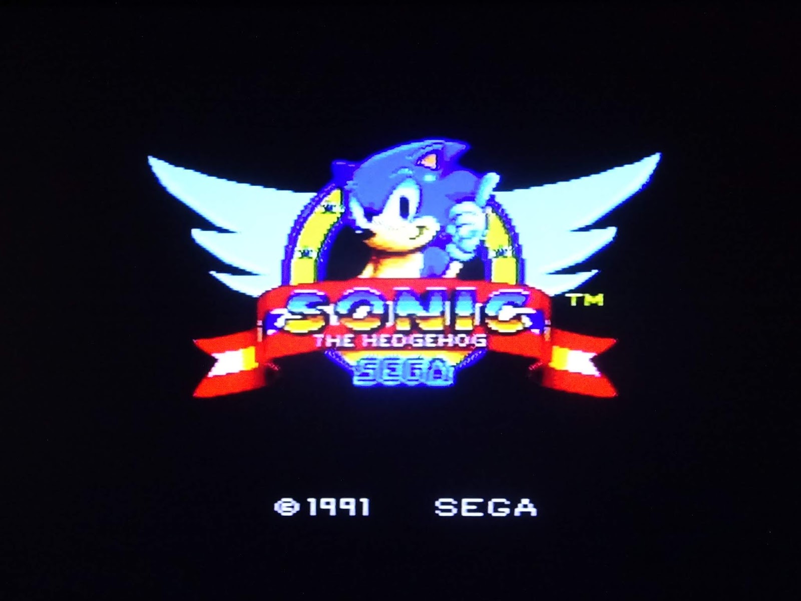
Zooming in on the screen, you can see a difference between composite....
.... and RGB.
It depends on your TV / monitor, but the composite version is still better picture than RF (if you can get the RF to tune in on a modern TV these days).
So if you fancy a bit of Master System, and the prices of the original SMS are a bit high, then a composite mod on an SMS II is a reasonable alternative.

Sunday 23 December 2018

Commodore 64 Joystick interferes with keyboard

I have been contacted a few times to fixes a particular fault on a Commodore 64. A fault that isn't a fault, but a 'feature' of the design.
The fault report usually goes along the lines of 'when I move the joystick, it also presses some keys'.
This can be seen if you plug a joystick into port 1 and wiggle it around, you will see a variety of keys pressed. Ignore the POKE 53281,0 - that is just to set the background colour to black. We have hit the limit of my photography skills, my camera just doesn't get on with the light blue on dark blue of the default colour scheme and merges them into one.
The phantom keypresses aren't actually a fault, they are caused by the joystick ports sharing the same pins used by the keyboard. Here you can see that part of the schematic in isolation.
The joystick ports are connected to the lower 5 bits of each of the 8 bit ports used to scan the keyboard. The joystick is just a series of switches connecting the up / down / left / right / fire lines to ground, and this is read by making those ports both into inputs and activating internal pullup resistors in the 6256 Complex Input Adapter. Any inputs which read 0 mean that lines from the joystick is active. The others read as 1 due to the pullups.
When the keyboard is read, the rows (port A of the CIA) are set as outputs, with each row pulled low in turn. The columns (port B of the CIA) are read in, any that are low indicate a key on the currently scanning row is held down. If there is a joystick in use in controller port 1, that can cause false readings as that also make one or more of those rows low when the joystick is moved or fire is pressed, giving the false readings above.
That's normally as much as needs to be said as that explains the extra characters on the screen. However, one repair request came in recently which initially looked like this, but proved to be a little more complicated. What was happening here was keys were stopping working after the joystick had been moved, and were staying disabled until the power was cycled.
Here I have typed 1234567890 several times, and after moving the joystick down, you can see that 3 and 4 stop registering. The keys W, A, shift, Z, S, and E also stoped, you can see from the matrix that these are all on the same row.
Those keys remain unresponsive, and when the joystick is moved left, more keys go, this time 7 and 8 (and also Y, G, V, B, H and U).
Again, a full row, and the row that corresponds to the pin on the controller port 1 pin that would have been pulled low by the joystick.
I know the joystick is fine, but I tested in anyway, and also tried several other joysticks including my 'joystick emulators', and the same effect was observed.
There was only one likely culprit here, U1, the 6526 CIA that connects to the keyboard and both controller ports.
The chip was soldered in, so just to make sure, I did try the Commodore 64 Diagnostics with loopback connectors. That initially confused things by saying that both CIAs were at fault, but detected that on the user port test.
That, however, turned out to be down to a bad connection on the edge connector, so I gave that a good clean and got it nice and shinny.
With the cleaned, it passed all tests, and did not detect the keyboard fault, I presume it was testing in the default state after power on when it works, rather than after the inputs had latched up (if that is what had happened).
I still thought the keyboard CIA was faulty, so I replaced it, the ran the diagnostics again to check everything was still OK. That passed OK, and back in BASIC, the fault was gone, no keys were being blocked after moving the controller in port 2.
I suspect that fault could have been caused by swapping the joystick ports when powered, or by static getting to the pins on the port from a carpet. I don't know for sure, just be careful with your controller ports.

If you want to support this blog, you can donate via Patreon or Paypal, or buy something from my store.

Sunday 16 December 2018

Commodore 128 Keyboard repairs

This is an old post, preserved for reference.
The products and services mentioned within are no longer available.

It's about time I did something about the keyboard on my Commodore 128D. It does the job, but there are a few issues with it.
Firstly, the + key is missing from the numeric keypad, and the key stem is broken.
And also, the Caps Lock switch is a latching switch and that is completely missing
The other issue is this is not the standard UK keyboard, it seems to be a German QWERTZ keyboard, with the alternates on the Z and Y keys.
The symbols keys are just mad though, what's going on there? 0 = and 0 again on the 0 key, * * and + and the * key, Eh? I just don't understand what is going on there, and it's a bit of a pain to find the right one when typing.
To help with this, I have a keyboard from a broken slightly yellowed flat C128. I'm a bit scared to remove that address label on the bottom as it looks to have been there a long time, so will probably be a different colour underneath.
This one also has issues. Caps Lock is present, but all the other buttons next to it are broken off. The top row of keys stick up the most, so are often the ones to get damaged in storage (or when being pulled out of a skip).
Apart from the function keys on the end, they are C128 mode only, and are not recognised in C64 mode (even the arrow keys are ignored). The 40/80 key is there, but again is alone in it's group, and also the switch is broken.
The function keys are all there, two of the arrow keys are missing and the ; ) key is stuck down and repeating.
The keyboards are actually almost identical, the main difference being the cable. On the C128D, this is a two foot cable with a 25 way D male connector on.
On the flat C128, it is a six inch cable with a sort of square 25 way D female connector on.
The same PCB was used for the flat C128 and the original C128D, with either a pin header for the internally connected keyboard on the flat C128 (below).
or a right angled 25 way D female on the C128D (above).
As with most Commodore keyboards, to do anything with these involves desoldering the connections to the latching switches (three of them on the C128 boards) and removing hundreds of tiny screws.
Whilst it's apart, it's a good opportunity to give the contacts a good clean.
Putting it back together, I added some tape over the place where the cables were soldered on. All the VIC20 / C64 keyboards had this from the factory, but neither of these 128s did.
The metalwork is identical, so I ended up swapping the PCBs around to make things easier. They both have the same mounting holes and angled sections etc. so it's was a straight swap. I used the key stems from the two top row arrow keys and the - on the keypad to replace the broken / missing ones on the good keyboard and to provide the most useful keys on the other.
I have rearranged things to give one standard UK keyboard with a full set of key switches, and one made from the leftovers, including all the QWERTZ keys with the extra symbols on. (and before anyone asks, I don't have any spare keys available. Every time I do a post like this, I get people asking for spare keys. Sorry, as you can see I've used them all)
I had been asked for a Commodore 128 USB keyboard controller, so that was another reason why it was a good time to run through this as I had it around for testing. I've built a few of these C128 USB keyboard controllers, but not enough to have done a custom PCB (yet), so this is adapted from one of the my generic boards with a 25 way D connector on a ribbon cable. I have used a 25 way D male IDC connector with the shell removed. It's not a perfect match for the pin header on the C128 board, but it works fine.
The board with the leftover keys has all the keys required for C64 mode, and the caps lock switch moved along with the 40/80 cap on it as the 40/80 switch is rather important - how many C128s are thought to be broken because 40/80 has been pushed down and it's in 80 column mode.....
That all tested fine, so will be quite handy as a keyboard for bench testing C128 boards, when I won't be too bothered about the extra symbols or missing C128 mode keys.
To test the good keyboard I will be using for my C128D, I used an alternate ribbon cable (if I tell you the 25 way D connector was purple, can you guess where it came from?).
That also tested all fine, so back into the case and it looks alright. A bit yellowed, but evenly so, and not obviously made up of bits of two keyboards.
I know I have tested it as a USB keyboard, but I wanted to retest it on the C128D itself.
That's all back together with the similarly yellowed C128D-CR and a 1901 monitor.
And yes, of course I tried out Rodman.
The CRT monitor is always nicer to look at, and clearer in the s-video and RGB modes the C128 generates, but I still tend to use pictures from an LCD monitor in these posts as it is easier to photograph, apart from in C64 mode, where the light blue on dark blue colour scheme rather confuses my camera.
Sometimes on these posts I end up with a folder full of unusable photos as I try to surprise the camera by coming at the screen at different angles.
Sometimes I give up and have to cheat and poke the VICs background colour register to black (see next week's blog post...)