Monday 29 December 2014

Commodore PET 8032 Update

This is an old post, preserved for reference.
The products and services mentioned within are no longer available.

Just a quick update on the Commodore PET 8032 Restoration. It's been generally working well, but I've had occasional problems powering up.  It would beep, but show nothing on the screen. No video signal, but everything else working, no response to blind tape commands. I finally traced this to the BASIC ROM set, with the editor and kernal working fine as it beeps, but the BASIC interpreter not starting.
I tried replacing the ROM chip with an EPROM, which worked a few times, but then had the same startup problem.
Pushing the top socket (UD9) one way or the other and then turning the power back on did seem to fix it. The board has the older style white IC sockets, which are sometimes problematic.
Technically, replacing it with a turned pin socket would be a better solution, but for historic and asthetic reasons, I wanted to keep the old style sockets. I could have used one of the two option ROM sockets, but again, that wouldn't look right. I could replace all of them, and may go down that route if there are any further reliability issues.
There is another white 24 pin socket on the board, the one for the character ROM,  UA3. That is at the other side of the board, below the DRAM chips. Half of the DRAM had failed and been removed and replaced with black turned pin sockets.
I removed the socket and replaced it with a black turned pin one. That tidied up that side of the board and provided a donor socket for the BASIC ROM.
With that replaced, it seems to start up with out a problem now.
Time will tell if this has fixed the issue.

2022 Update: This PET is still working well, no further problems with the ROM sockets.

Tuesday 9 December 2014

Commodore PET 8032 Repair and Restoration

This is an old post, preserved for reference.
The products and services mentioned within are no longer available.

Oh dear, here we go again. Hopefully this won't take as long as my previous Commodore PET 4032 restoration.
This is a Commodore CBM Model 8032, from around 1980/1981. The model is given as 8032-32 B. That is 80 column, 32K, business keyboard.
It is the earlier version of the 8032 with the larger section between the monitor and keyboard. This ebay score appears to have been used for spares, many of the parts are not fixed down, and at least the main board is not the original.
The board is not bolted down, and is the later universal 40 or 80 column, 16K or 32K board, dating from 1983. It is also not working. I will fix this board later.
For the moment, I have another ebay score, an 8032 board form late 1980.
This is the style of board which would have originally been fitted. It was also faulty, but I repaired it in preparation for this.
The transformer is the right type, but not bolted down, and it looks like the monitor lead has been reconnected at some point, and the attached capacitor wasn't clipped down. So this may well not be the original.
The capacitor is marked as being made in West Germany, where as the serial number sticker on the back of the case is marked made in the USA. Pets were built in both locations, so I suspect the power supply came from a German produced unit. The capacitor was rattling around loose and is a bit dented. It should be 22000uF, with had a stated tolerance of 0/+50%. It is now reading 29830uF, still well in spec and low ESR. Not bad for a 35 year old part (far better than modern capacitors which tend to be one of the main causes of failure of consumer electronics these days).
The power connector is a bit mangled, it looks like someone has tried to fix it by squashing the wires down. Given the damage to that, I have replaced the plug.
A useful tip in this situation is to do this one wire at a time, to minimise the chance of making a mistake. Pin three is left blank for polarisation.
I'm assuming the monitor and keyboard are original, as all the screws are all present and tight. The monitor is an earlier version to the one in the 4032 and 8032SK, but required less clean up that the 4032 monitor.
There were a few issues with the monitor. it was out of adjustment, over bright and the vertical hold had slipped.
The text on the screen was intermittent, down to a dry joint on the video connector. With that fixed, and the monitor adjusted, it was working fine.
The keyboard wasn't too bad, about 90% of the keys were working, but I still went for the full strip down and clean up as with the 4032 keyboard.
As usual, the keycaps were removed and washed, and the PCB cleaned and reassembled.
All keys were working again, a bit yellowed, but fine.
The base cleaned up quite nicely, no need for a respray this time.
The power supply and board were installed and tested. All working well.
The upper case was a bit dirty, but cleaned up. From inside, you can see the extra space in this model hides two slots that look like they could have been for dual floppy drives, but they aren't the right size.
The cleaned case was reassembled with the piano hinge and bonet prop.
I'm replacing fixing where they are missing or tarnished, and cleaning up as I go.
The monitor was reinstalled and the whole setup tested together. After a few runs of memory testing and a long soak test, it's working very well.
So there is another computer restored. Quite a few faults in this one, the monitor out of adjustment and with a few dry joints. The keyboard needing cleaning to get a few keys working. The power supply plug mangled, and the mainboard faulty (to be repaired later).
Here you can see the differences between the 8032 on the left and the 4032 I previously restored, on the right. The the higher monitor stand, the business vs graphics keyboard and the 80 vs 40 character screens. I have to say I prefer the white coloured monitor bezel on the 4032, but they are both very nice machines.
Inside, the different transformers and boards can be seen, and the higher back on the older unit.

Now all I need to do is get a PET 2001 (and a bigger bench)....

Saturday 6 December 2014

Commodore 8032 Main Board Repair #2

This is an old post, preserved for reference.
The products and services mentioned within are no longer available.

Here is another Commodore CBM 8032 board to be repaired. This one is slightly later than the previous 8032 board I repaired, but earlier than the universal dynamic PET board in the long running 4032 restoration saga.
Like the other early board, it is 80 columns only, but jumpered for 16 or 32K. A few other differences from the later boards. There are three voltage regulators, two 7805 and one 7812. Later they dispensed with the two 7805s (5V @ 1A each) and replaced them with a single LM323K (5V @ 3A).
The earlier board had gold plating on all three rear edge connectors, but not the side datasette 2 connector. This one like the remainder of the PET boards has gold plated IEE488 / GPIB connector and the rest solder tinned. There is also space for a pin header for the GPIB port. It was populated on the earlier board. Here it isn't, and in later boards it was removed altogether. These earlier boards had the cassette transistors riveted down. Later boards they are left floating in the air.
They also tend to have white sockets on the ROMs and the five main chips. Being white it stands out even more that all five 40 pin chips are all missing. The ROMs are present, and there is a ceramic version of the later 901465-23 BASIC 4.0 ROM.
As you will see from the keyboard and video connectors above, it is not in the best of condition, most of the pins are bent.
It does however, have the same symptoms. Nothing on the screen. No beep.
Obviously one reason it doesn't beep is the piezo disc is missing, but it's probably a lot more than that.
The RAM is made up of 16 ceramic MM5290J-4 4116 clones. These had very long legs which were all mangled and shorting on the rear. Forgot to take pictures of those, but I did clip them all short. The lid of one of the chips was rattling around in the bag when it arrived. All of the bits must have all fallen out.
When I desoldered the chip, all the legs just fell off and left the die and the bottom of the case
The first job was to tidy up all the pins and replace the piezo and the damaged DRAM chip. Powering on with all the chips removed passed, so no problems with voltage or shorts on board. .
Next, a working set of 40 pin chips, from left to right, 6520 (GPIB PIA), 6522 (VIA), 6502 (CPU), 6545 (CRTC), 6520 (Keyboard PIA). After testing, the 6520's were replaced with new WDC 65C21N's, and the 6522 with a new 65C22N.
Time for the ROM / RAM replacement board. That booted fine, but failed with either onboard ROM or RAM enaabled. Some of the DRAM chips were getting very hot, particularly the bottom few, so I started to replace those.
It was at that point that I found that more of the DRAM chips were falling apart. The lids just peeled off. Eventually all of the lower 8 chips fell apart. The top 8 were seemingly intact.
Inside, 16384 bits of DRAM. You can just see a few loose bonding wires in the way.
With those replaced, the RAM tests passed.
The ROMs were next. I'd found the monitor ROM 091474-04 was also hot and not working. Replacing that, the ROMS were fine, and the ROM/RAM board could be removed.
That's complete and has been on soak for a few days with no problems. Another one back in service. I have something lined up for this board in the coming weeks.

Update: This board has now found it's new home in an early 8032.

Saturday 29 November 2014

BBC Micro Issue 3

This is an old post, preserved for reference.
The products and services mentioned within are no longer available.

I recently won a BBC Micro issue 3 board and case on ebay. One of those situations where the seller decides they could make more money if they split it up and sell the parts separately. Not my favourite tactic. I didn't see the power supply on there, so it may have suffered from exploding suppression caps. A common issue on BBC micros, and an easy fix.
I was going to insert a link to my previous article about BBC power supply repairs. I've done loads of them, but it seems I've never written a blog post about it. I'll make a note to do that with the next one.
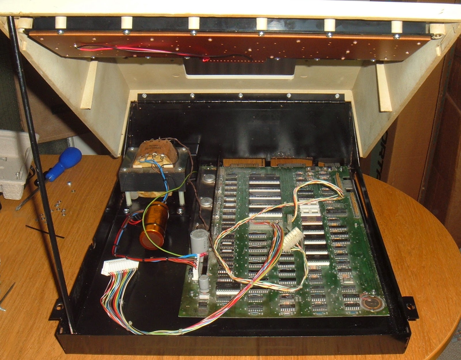
So this is what I got, the case and the main board. The aren't many of the very first BBC computers, issues 1 and 2. The issue 3 was the first to appear in quantity.
After that, there were lots of issue 4's. Issues 5 and 6 weren't released. The issue 7 was the final and most prolific release, and most of the BBCs I see tend to be issue 7's, with the occasional issue 4. I don't have a complete issue 3 machine, so now is the time to make one.
This is one of the machines produced by ICL, so has an ICL serial number, rather than the standard Acorn one.
The main board appears to be in reasonable condition.
It would have been a model B, as it started with all the connectors fitted and 32K of RAM, as 16x Fujitsu MB8118-10 (4116 clone) DRAMs.
Well, I say 16, 15 of them were like that. One has been replaced by a Hitachi HM4816A. Based on the date codes, it would have been produced in early 1982.
Continuing the industrial archaeology, it would appear that the system 6522 VIA was replaced some time after 1988 with a Rockwell R6522. Below that, it look like in 1984, it had an Intel 8271 floppy disk controller upgrade fitted. The 8271 used the older FM (single density) encoding, so had a maximum capacity of 400K for a double-sided, 80-track disk, accessed as two separate sides. Soon after the release of the BBC, add on kits became available which used the cheaper and faster WDC1770 floppy disk controller, which also had double the capacity using  MFM (double density) encoding (thanks to Alex Taylor for the correction).  The 8271 is one has the one it was originally designed to take, and even the much later model B+ has been designed to take either the 8271 or the 1770. (yes, model A, B and B+ may sound familiar to Raspberry Pi fans, but the BBC was first by about 30 years).
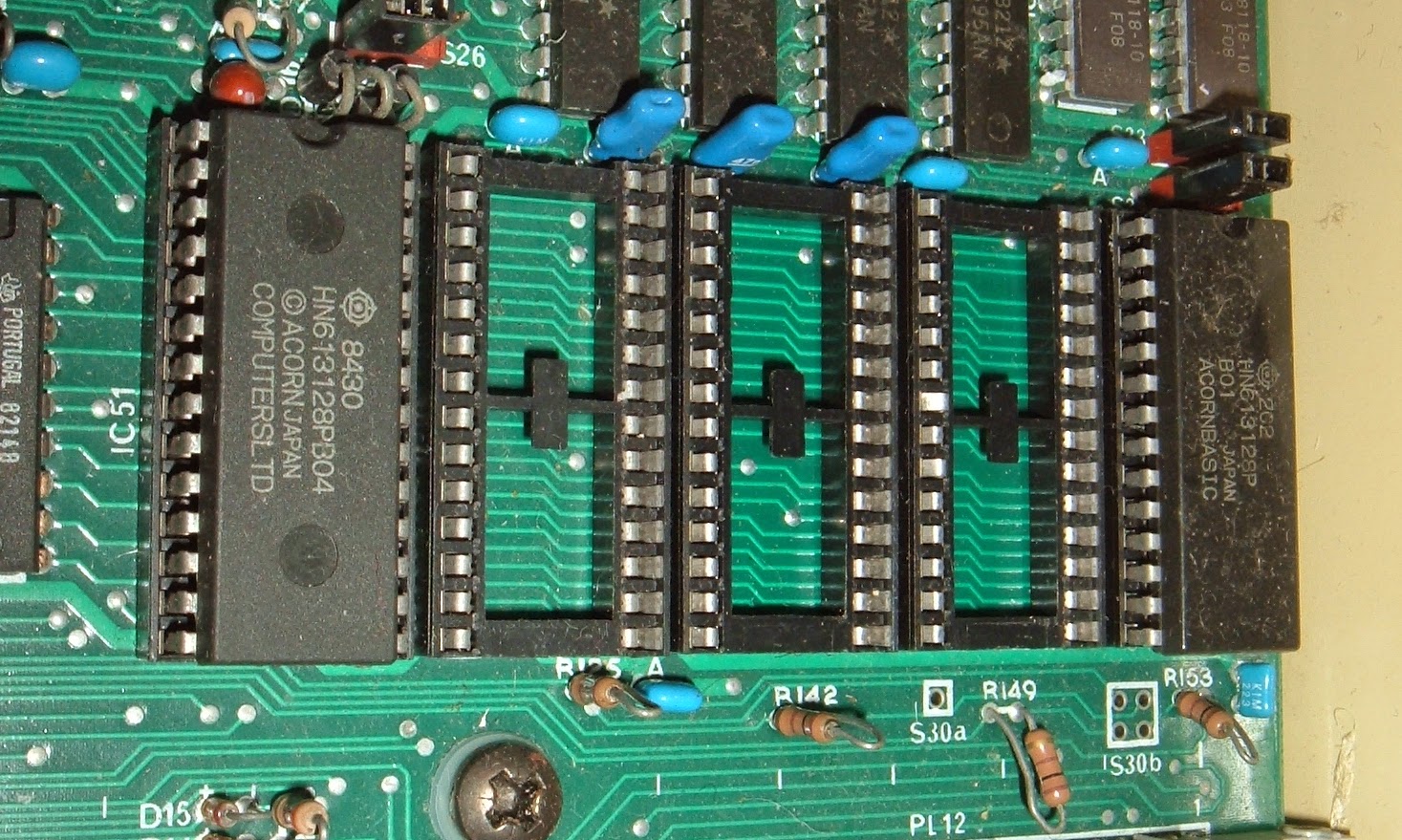
The BBC has 5 ROM sockets. The one on the left is the 16K OS ROM. The other 4 are paged 16K ROMs, which one is selected is based on a register. The BBC can access any one of up to 16 ROMs, although only 4 sockets are provided. With a simple wire modification, it is possible to use 4 64K EPROMs, each with 4 images on to get all 16 ROMs. Again, I thought I'd written a blog post about this. I'll add that to the list as well. The board underneath two of the sockets looks suspiciously clean, the ROMs in there were probably sold off separately as well.
The one on the right is BASIC. There should have also been a DFS ROM to go with the 8271 floppy disk controller, so I've burned one.
Since this is going to be an assembly of parts, I've decided to keep it as an issue 3 machine. The 6502 CPU and the user port 6522 VIA are the usual Synertek branded chips, and the original system 6522 would have been the same. So I replaced the Rockwell R6522 VIA with a Synertek SY6522 to match.
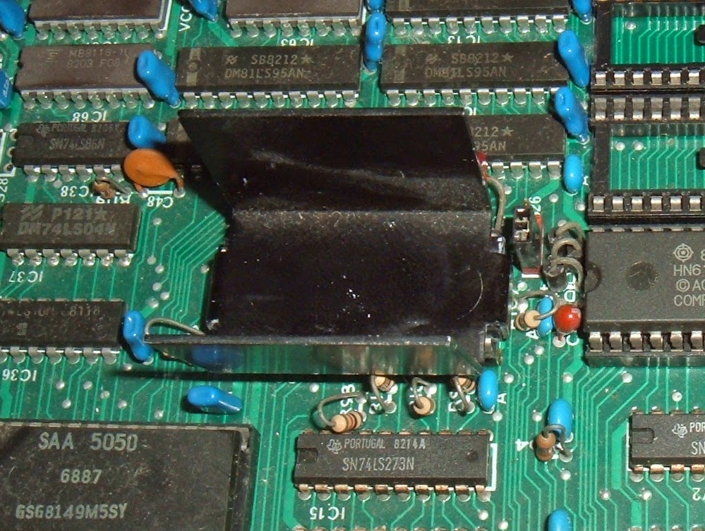
The Ferranti video ULA has also been replaced with a VTI VC2069, as would have been used on issue 7 boards. Again, I have decided to roll this back to the it's original state.
The Ferranti ULA is less efficient than the later one, and needed a heatsink.
With fresh hearsink compound applied, that's the board sorted, now it needs a power supply.
Later BBC micros had switch mode supplies, but the early BBC micros had these black linear power supplies. This is one I've had for years, I was given this as it's owner replaced it with a switch mode one. The linear ones do not have a disk drive power connector, and the owner wanted to power an external drive. Only 20 years later, I finally have a suitable case for it!
The power connector for the BBC main board is unusual. Rather than one plug and thick tracks going around the board, they have three pairs of 0V and 5V  connectors which attach at various points across the board. The red and black are marked 0V and VCC.
The brown is -5V, but the label seems to be missing the - sign. That's one to watch out for.
That's the power installed, time for a keyboard. Some of the early ones had a DIP switch installed bottom right. I have one of those somewhere, but the PCB was poorly etched and it's a bit intermittent. This is a spare one, I think from an issue 4.
There are a few differences at the back of the case, compared to later versions. The wording is different. Here Allen Boothroyd is credited. On later machines, that is moved to the bottom of the case. The ventilation slot is a lot larger, it was reduced in height later on to stop small fingers getting inside. This looked like it might have been taped up at some point,but that cleaned up ok.
Note also the reset switch is labelled. All machines have space to install a reset switch, and a hole in the back, but I don't think there were ever fitted. Only the early ones have it labelled on the back, the rest have it covered up. Like the Econet port, this would have have a plastic cover, but it has been punched through at some point. Most of them have. I've put a piece of black card to cover the holes.
The BBC was well designed to be expanded and serviced. There was always one annoying part which was the BNC video jack. That had to be desoldered to removed the board, and often didn't get reattached if the owner was using an RGB monitor.
I was surprised to see this version had a removable connection, using the same spades as the power supply. Shame they discontinued that in later revisions.
The board appears to be laid out to take a PCB mounted BNC socket, but I've never seen one fitted.
Underneath is the usual collection of IDC expansion connectors. The power out is marked, but there is no socket on the linear power supplies. There is also an ICL serial number sticker matching the board.
The lid was a bit dirty, but cleaned up alright. The other thing that usually gets pushed out is the slot on the side of the keyboard. This was designed for plug in modules to expand the speech chips, and some third party add-ons use the hole to add a ZIF socket connected to one of the ROM sockets. Again I covered it was a bit of card. I also replaced the perspex cover strip with a slighly clearer 'BBC Microcomputer' legend. Later BBC's said 'British Broadcasting Corporation Microcomputer'.
It looks a lot yellower in the photos. It doesn't look too bad. So there it is, an assembly of parts from various sources, but something like an issue 3 model B.
Oh yes, and it works. BBC's usually do.