Way back in 2017, The Future Was 8 bit was in the process of launching their divMMC future.
To make batch programming of those possible, I designed a rig which would allow 4 divMMC devices to be programmed at a time. This had an impressive looking control box with big buttons and lights and cables and everything.
http://blog.tynemouthsoftware.co.uk/2017/04/divmmc-programmer.html

It utilised four Spectrums, specifically four ZX Spectrum +2 grey boards. Assembled from various spare and broken boards.
Read about the repairs required to get those four boards up and running:
http://blog.tynemouthsoftware.co.uk/2017/06/spectrum-128k-2-grey-repairs.html

Six years on, and the rig is still in regular use programming divMMCs, but a few of the boards have failed and have been replaced with others or taken out of service.
Ahead of a impending large batch of divMMC boards to program, I have been sent the faulty boards to see if I can bring them back to life.
Four boards have arrived, and have numbered them 1-4 on the serial connector on the back of the board.

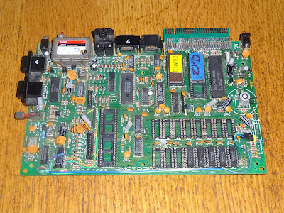
Board 1

This shows off some of the modifications that have happened to all the boards in service.
I designed a small extender board which is soldered to the edge connector, providing a better connection. If / when it wears out, it can be desoldered and a replaced with a new one.

One of the benefits of using the Grey 128K +2 boards is they have RGB and composite output on the DIN connector. The RF modulators are no longer used, and have been fitted with power LEDs instead.

The LEDs were installed as there had been some problems with bad connections on the power connectors. These had been desoldered and fitted on the back of the board for better wire routing.

The 3 pin connector was originally where the regulator was connected, but since the pinout was 9V in, ground, 5V out, it was repurposed for these boards as 12V in, 0V in, 5V in from the external power supply.
I will look at replacing those connectors as part of these overhauls.

The original Molex KK connectors are 2.54mm (0.1") pitch, so there are a few options, and I have gone for JST XH. These are the same pitch, but I like that they gave multiple points of contact between the crimp and the pin, rather than the single point with the old Molex types.

To simplify things during testing, I went back to the original idea of using that for a regulator, rather than as power input, but I went for a DC-DC converter rather that the original 7805 on a big heatsink.

This board has all the original RAM chips. Well, there's ya problem. At least, I expect it will be.

Power it on gives a black screen. So yes, most likely a RAM fault.

There is a RAM tester ROM in one of the other boards, so I will borrow that and give that a go.

Yes, bad D0, which could mean one or both chips on D0. And also any of the others, since it only shows the first one.
Lets leave that one for a moment, and move onto board 2.
Board 2

This one has was one of the first four, as seen by the 2 sticker on the joystick port.

Like many of the boards in the rack, it is running a replacement ULA, a vLA128 (https://vdrivezx.com/vla128/), trying to save wear on the original ULAs where possible. I was going to give these a full run through, but didn't have time. From what I can see, they did everything the original did without a problem, so an ideal drop in replacement.

In the last repair, quite a few RAM chips were identified as bad and replaced.

I normally try to match brands of RAM, but I didn't have any of the Samsumg KM4164 chips spare when I did that (still don't, for reasons which will become clear as we progress.....).
Another black screen, another RAM fault. D0 again, one or both of those, or more. And neither of those are socketed (yet).

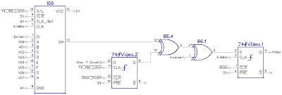
This is a diagram I made for the previous post, so you can see where the D0 chips are and the sockets are not.
OK. I am starting to see a pattern here. Let's try board 3.
Board 3

Well, OK, maybe not. This board has already been harvested for parts. It must have been taken out of service a while ago as it does not have the power LED or rear mounted connections or edge connector extension.

Looks like it has already had the RAM repaired a few times before, originally with the dual wipe sockets, and later by me with the turned pin ones. And has since had several chips stolen.

But at least it had the RAM test ROM chips, which I had already been using on the other boards.

I populated the missing RAM chips and gave it a test.

D7. Bad. Two chances, one of which was socketed.
It wasn't that one.
OK, Maybe board 4 then?
Board 4

Another of the original repairs. This one was missing a ULA, and also it seems I had taken the "nuclear" approach and socketed all the RAM on this one.

I borrowed a ULA and was about to power it on before I had a further look at the RAM chips and realised they were all upside down. Not sure how that happened? (I think TFW8b might have had a late night go at fixing this one.)

And worse than that, three of the chips bore the MT logo of a Micron Technology RAM chip. These are often found in Commodore 64s. Broken Commodore 64s. Rarely found in working Commodore 64s.
I turned them all around and ran the test.
And of course, they failed. Sorry, I had already given up taken pictures of the screen at this point, but you can guess what it looked like.
Lots of bad RAM
It seems all the boards have the same problem, bad RAM, probably quite a lot of it.
I used a ZIF socket for D0 and tried out chips in there one by one to see if it showed D0 bad or not. From that, I managed to find 8 working chips

Only the bottom row is required to boot, this contains the lower 16K of RAM plus the odd numbered banks of RAM.

I kept going until I had a complete working set.

Finally, the RAM test passed.

I will skip over quite a lot of time here, I went though this cycle quite a few times.
while (faults > 0)
{
IdentifyBadChip();
DesolderBadChip();
SocketBadChip();
InsertGoodChip();
Retest();
}
I got to the stage where I concluded that the best option going forward was to remove ALL the RAM and fit sockets. I wouldn't normally do this, but since these get a lot of use, it will be easier in future to swap out faulty chips.
These are nice boards to work on, the PCBs are good quality, so desoldering chips is fairly easy, other than a few bend over legs on each chip. Most chips fell out as the last leg was desoldered.

I did at one point consider I might be able to get away with just 8 chips, which would only give a 16K machine, but I don't think that would be enough to run the flashing program, the 8K divMMC ROM image and the screen RAM.

I ended up fitting the full compliment of sockets to boards 1, 2 and 4.
Board 3 was missing various parts already, and also did not have the upgrades of the others, so that one gave up it's remaining RAM chips to help the others.

Between the four boards I had quite an assortment of RAM chips. Various makes and speed grades.

These are all the remaining Samsung KM4164B-15 chips, sorted by date code.
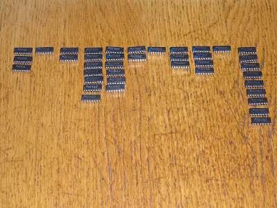
I had already discounted some Samsung chips with a different speed grade (-12 instead of -15), the MT parts and Toshiba parts which didn't match.

After all the tested, I ended up with 10 bad chips (although a further few failed in soak testing).

I had enough chips to populate two of the boards, and do some more testing.

It's a hard job, but someone has to do it.

That's board 2 sorted.

Board 1 also got a full set of chips, but started behaving strangely in soak testing.

It would run the test, pass then the screen would flash blue and then reset.

I wasn't sure what was going on, so I tried swapping out all the RAM with a known good working set (Toshiba chips, not Samsung).

That did the same, so the RAM was probably OK.
I tried swapping the RAM mux chip (Amstrad 40058, next to the Z80), but that made no difference, same with the ULA.

It was only when I swapped the Z80 that the problem went away.
I was also able to create the same problem on another board by installing the bad Z80.
Fitting a new Z80 solved the problem.
I don't know the origins of the part that was fitted, but were NEC really making D780C (Z80 clones) in 2006? or is this a remarked 1980s part?

With a new Z80 (OK, with the old Z80 stolen from board 4), board 1 was now also working.
Board 4 has also been tested, but has been sent back with the last 5 working Samsung DRAM chips, no Z80, ROM or ULA, but can be used as a replacement for any of the other boards, should they fail. And also the two test ROMs that TFW8b sent.
Board 3 is staying with me as a parts board for the moment. And oh look, someone has already stolen the AY-3-8912 for a previous blog post they were writing on AY-3-8912 sound cards for the Minstrel 4D. I wonder who that was?

I think it would helpful to buy or make some replacement plug in RAM modules, as those chips seem to be getting on a bit, and failing in their old age.
Advertisements
DivMMC Future
The DivMMC Future is avaiable from The Future Was 8 bit
https://www.thefuturewas8bit.com/shop/sinclair/divmmcfuture.html

Patreon
You can support me via Patreon, and get access to advance previews of posts like this and behind the scenes updates. These are often in more detail than I can fit in here. This also includes access to my Patreon only Discord server for even more regular updates.
https://www.patreon.com/tynemouthsoftware