
I knew I said I was going to start on the Mini VIC development logs, but I found one more from the Minstrel 4D development, this from September 2022.
Throughout most of the Minstrel 4D development, the video circuitry has been pretty much lifted from the Minstrel 4th.

The same chips in the same configuration, the main difference is the Minstrel 4th had jumpers for PAL/NTSC and normal/inverse, and the Minstrel 4D uses DIP switches for these.

On the original (green) prototype, the DIP switches were up next to the video section, but were later moved to the middle of the board.

I knew that this worked, so could be left alone. However, I set myself a "stretch goal" that if I had time, I would revisit it. I'm still recovering from some health issues, so as a gentle ease back into doing work that required concentration I decided to completely rewrite the code from scratch.
The Minstrel 4th video chip was ...
Hang on, let me just stop for a minute and fix something. I don't like calling it the video chip, it does not actually generate the video signal. That comes from video RAM, feeding font RAM, feeding a shift register, just like in the original Jupiter Ace. Just with a few additions such as optional inversion and a pixel synchronisation flip flop.
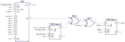
The microcontroller generates the video sync and controls the timing of the other bits, the latches, flip flop and shift register. It also counts generates the addresses for the video and character RAM, and just replaces few dozen or so logic chips that originally did the clock, counting and decoding.
I prefer to refer to it as a CRT Controller, a bit like a modern version of the 6545 CRTC used in the Commodore PET etc. I refereed to it in the Mini PET schematics as a "I can't believe it's not a 6545".

The original Minstrel 4th CRTC was developed around the same time as the Mini PET version (I can't actually remember now which one came first), and they share a lot in common.
When I designed the Mini PET 40/80, I revisited the PET code and ended up rewriting it completely. The extra steps required to support 80 column video output would have required a lot of changes anyway, but I wanted to make two main changes to the original code.
- I wanted to switch to using a timer interrupt to set the horizontal sync pulse at the start of each line. That would keep the timing a lot more consistent, and required less counting of cycles to make sure each code path took the same number of cycles, as I had previously done.
- The original version had tried to copy the video output generated by the Commodore PET, and other machines of that era. I wanted to improve on that and generate a more correct composite video signal.
I don't really want to get into how the whole things works at this point. I will have to do that again at some point. I say again, as I wrote a huge long scrolling blog post covering all the ins and out of how the Minstrel 4th and Mini PET video worked. That was about 90% complete when it all got wiped due to a bug in blogger. Still bitter about that. Still haven't summoned the energy to do it all over again.
(I did write quite a lot about in for the Minstrel 4th manual, I may adapt and extend that into a blog post at some point)
The reason for point 2 above is that some monitors (it seems mostly ones made by Dell), do not like the simplified style of composite video generated by machines of this era. Everything else seems fine, old CRTs, and most modern LCDs, it is only the Dell ones that dosn't like it. Is that the signal's fault or the monitor?

This photo from George Beckett shows this issue (George is currently doing sterling work putting the Minstrel 4D through it's paces).
All the monitors ancient and modern that I tried it on here did not show this problem.

One line of an 8x8 character on the screen takes 8 clock cycles to draw. Get the timing out by just one clock cycle, and the character appears 1 pixel to the left of where it should be. I can make that happen by removing a critical NOP instruction.

That's just one pixel, it then takes at least 8 lines to get back, hence the slight bend rather than a step.
I have been through the timing of the original code and I cannot see anything out of place like that,(although if there had been, it would have affected all monitors anyway).
I think the issue is due to the vertical sync section of the video signal. The simplified version used on the Mini PET and Minstrel 4th (and most 8 bit machines in the 1980s) has the composite video signal go low for the entirety of the vertical sync segment.

For a period of 8 lines (8 x 64μs = 512μs) the signal simply goes low, as it does for 4.7μs at the start of each line for the horizontal sync pulse.

My intention at the time was to create a video signal the same as the PET or the Jupiter Ace, so I went with that form of signal. More correctly, it should maintain horizontal sync pulses in a specific pattern of pulse lengths during this gap, although none of these machines did that back in the day.

That means there is always a sync pulse to lock onto every 64μs - could the lack of those be what is confusing the Dell monitor?

I had added a programming port on the prototype PCBs, so with the scope hooked up for composite video shots, a logic analyser for timings and a USB TinyISP to program the chip, I was all set to update the code.

I was hoping it would be a fairly simple process of taking the Mini PET 40/80 code, removing the RGBi, PET monitor options and just leaving the interrupt based composite video with the correct vertical sync pulses.
It wasn't.
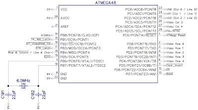
The Mini PET 40/80 CRTC runs at 16MHz, whereas the Minstrel 4th CRTC runs at only 6.5MHz, so there are only 40% of the available cycles to do things between the various sync and timing signals that need to be generated.
That is quite important when it comes down to such critical timing as this. I did consider moving to a 13MHz crystal to make this twice as fast, but I couldn't get hold of any at the time, and would have needed to add an extra flip flop to divide it down for the 6.5MHz / 3.25MHz used on the board.
There was also an added complication that I hadn't thought about. The PET uses white characters on a black background, so the edges of the screen are all at the black level, you only get peaks where the characters are. This means there is always black around the borders, which acts as a back porch for the video signal. (these are sections between the sync pulses and the actual video data that set the black level. White is the highest part of the signal and these set where black is, about 20% of the signal height - see a previous blog post about adding a back porch to the Minstrel 2 for more information - http://blog.tynemouthsoftware.co.uk/2017/01/minstrel-zx80-clone-video-output.html)
The default option on the Minstrel 4th is black characters on a white background, so the signal needs a back porch and a front porch to set the black level, then the rest is at the white level.

At the end of the visible lines, there is the front porch (don't blame me, I didn't come up with the names). This is 1.65μs of black level just before the horizontal sync pulse takes the signal low.
On the Mini PET 40/80, I used this to set an interrupt that would fire when the horizontal sync pulse was due, so that was always at a precise time.
With the slower clock, 1.65μs is only 10 instruction cycles (one cycle at 6.5MHz is 153ns). That doesn't give enough time to set and wait for the interrupt.

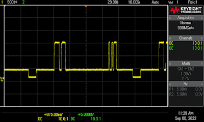
This shot was taken during development, and you can see the top border where I have started the front porch too early, and the rest of the lines where only the character sections are at white level.
In the end, I changed the code so the interrupt occurred at the end of the visible line, the start of the front porch. (ah, see, the name makes more sense that way as well). That was always a fixed length, so the sync pulse was still starting at a consistent point.
There is an awful lot of staring at traces like these checking that each of the lines add up to 64μs, and all the syncs line up.

But it is coming together now, all correctly lines up and working fine on my monitor.

These pictures are a bit grey as I have the brightness turned right up so I can see if there is anything visible around the sides of the picture.

The new more compliant video seems to have met with the approval of the problematic monitors, and everything is looking good now.

Advertisements
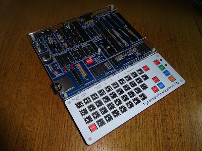
Minstrel 4D
The Minstrel 4D kits are shipping now, you can order one from The Future Was 8 bit - SPECIAL OFFER - £15 off the Minstrel 4D and free shipping to the USA
https://www.thefuturewas8bit.com/minstrel4d.html
More info in a previous post:
http://blog.tynemouthsoftware.co.uk/2022/08/minstrel-4d-overview.html
Patreon
You can support me via Patreon, and get access to advance previews of posts like this and behind the scenes updates. These are often in more detail than I can fit in here, this post contains bits from several Patreon posts. This also includes access to my Patreon only Discord server for even more regular updates.
https://www.patreon.com/tynemouthsoftware
