
Last time I looked at the many variations of the 40 key 8x5 matrix keyboard found on many 1980's home computers.
The original Spectrum keyboard is of course a style icon, but it wasn't great if you were doing lots of typing. Or if you were trying to work out what sequence of keys was required for an obscure keyword. There were an awful lot of things to fit onto only 40 keys.
There was quite a market for replacement keyboards for the ZX Spectrum back in the 1980s.

Even Sinclair got in on the act and upgraded the Spectrum case to make the Spectrum +.

The board inside was the same though, with the extended keyboard plugged into the same 5 way and 8 way connections, so still only able to support 40 keys.

The 40 key matrix was arranged as 8 rows of 5 keys, with the rows being fed from the address lines via reverse biased diodes and the key columns being pulled high before being sampled by the ULA.

To give an example of how this works in practice, lets look at a single key in that matrix. The pullup resistor is shared with the other keys on that column, and the diode is shared with the other keys on that row.
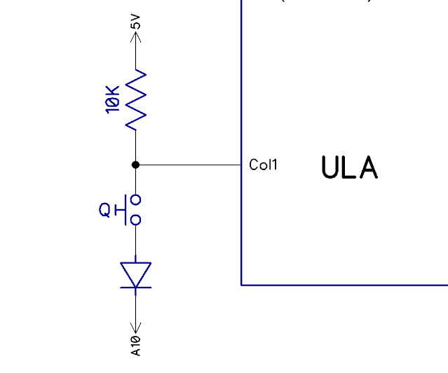
When the keyboard is being read, the upper address lines provide the scanning pulses. To test the row that Q is on, A10 is set low.
If the Q switch is pressed, the low A 10 pulls down the column signal and a low is read by the ULA. If the Q switch is released ("Neutralise the Q switch"), the input is pulled high by the resistor and a high is read.
So that is 8 columns and 5 rows, so 40 keys. How can you get more without changing the Spectrum board or ROM?
The rest of the new switches on the Spectrum + were combinations of other keys. For example, Edit is Caps Shift and 1 pressed at the same time.

The Spectrum + used a trick membrane with two additional layers so that when you pressed one of the 'special' keys, it actually appeared as if you were pressing two keys. This we entirely mechanical, no electronic or software changes.

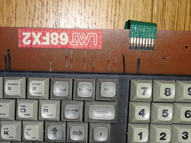
But there were many replacement keyboards, such as this LMT 68FX2 I was sent in for repair a while ago. I guess LMT is the manufacturer, 68 probably refers to it having 68 keys. Not sure about FX2. It has effects, too

This used individual key switches and added all the extra keys on the Spectrum + (and a few more). It did this with only the original 40 key matrix connections, 8 rows and 5 columns. How did that work?
Some keys, such as Edit above are easy, both the keys that need to be pressed are on the same column, so with two extra diodes, you can achieve that with a single key.

This will pull column 1 low if either row 1 or row 6 are low, making it appear if "Caps Shift" and "1" were both pressed and registering as "Edit". Looking around the board, you can see lots of diodes used in this way.
That takes care of all the keys on the same columns, Edit, Delete, Break and semicolon.
When the keys to be pressed are on different columns, this technique can't be used. So how do they do it? The answer is on the back, there are lots of transistors, which is how the other keys are achieved.

The transistors are bridged across the keys that need to be pressed and when switched on, will allow current to flow as if the key was pressed.

Here when "Caps Lock" is pressed, the two transistors give the effect of pressing "2" and "Caps Shift" at the same time.

The second transistor base has multiple connections as "Caps Shift" is required for many of the combinations.
One thing that intrigued me here was this required a power source, and the keyboard had no additional connections, only the 8 rows and 5 columns?

I did a bit of reverse engineering to find out what was going on. I flipped the image and labelled the keys with a custom childish hand-drawn font specially purchased at great expense for the occasion.
The power supply is generated on the top left of that diagram, three diodes and a resistor.

This taps power from the column lines, which each have 10 K pullups to 5V on the Spectrum board. Apparently three of the five was considered sufficient. I'm pretty sure it is columns 1,2 and 3. It would have made more sense to use columns 3, 4 and 5, and miss out 1 and 2 which include the shift keys. A capacitor would also have helped, but I couldn't see one.
I have combined all the elements into one diagram to show how it all comes together, it's really quite clever.

So the 10K pullups inside the Spectrum are fed via three diodes to give a positive voltage reference. This is further current limited by the 1K2 resistor. When a 'special' key is pressed, this is fed via diodes to the base of two transistors. Each of those allow current to flow through from a 10K pullup to one of the high address lines, if that is being drive low. (oh yes, and at least one of the 10K pullups on the left could be one of the ones on the right being pulled low, but that over complicated the diagram and was too much for my brain to process)

This does mean the address line is sinking a bit of extra current, but this is via a 10K resistor, a diode, a 1K2 resistor, the switch contact resistance, another diode, a transistor base-emitter junction and finally another diode, so that's probably fine.
So it turns out there is rather a lot going on inside one of these external keyboards with magical extra keys. The extents you have to go to at times to avoid changing an existing part of a system.
Next week
In what will possibly be the final part of this series, I will be looking at ZX81 external keyboards, and finding out why they don't work on a ZX80 or any of the Minstrels.

Advertisements
This post is an updated version of a post from my Patreon. If you want advance previews of posts like this and behind the scenes progress on new projects, you can follow along and support me on Patreon:
