As far as I am aware, most users order a divMMC future from The Future Was 8 bit, they plug it in and it works first time.
Occasionally, we hear from users that have problems, so I thought I would cover some of the troubleshooting steps we go through.
First I should cover normal operation, as sometimes that is all the problem is.
- Is the Spectrum switched off? Good.
- Is the edge connector clean? Good.
- Do you have an SD card with the appropriate files on? Good.
Now put those all together and switch on.
You should see a black boot screen for a few seconds, with several lines that all show OK.

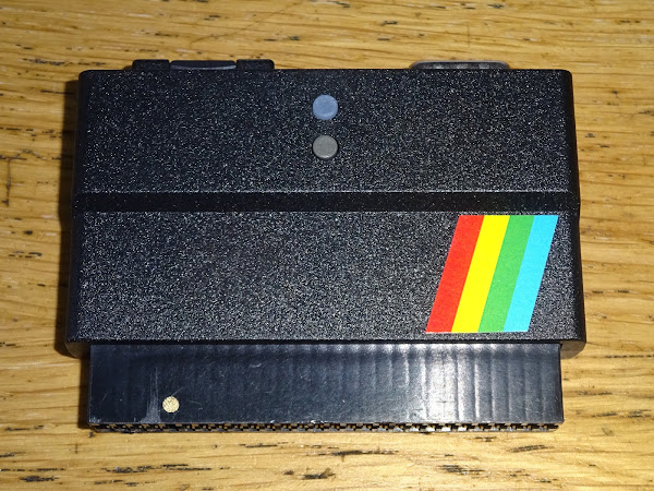
You then press the button illuminated red on the divMMC. (the non-illuminated one is reset)
That should turn green and bring up a file browser menu.

From there you can select games to load using arrow keys (CAPS SHIFT + 5,6,7,8) or a joystick plugged into the divMMC.
Select your program and away you go.
Troubleshooting
If that does not happen, let's look at some of the potential causes.
Sometimes it can be simple things, such as
- Pressing the reset button on the divMMC instead of menu
- Pressing 5,6,7,8 without CAPS SHIFT
- A broken joystick
- Joystick with autofire activated
- SD card empty / wrong files / wrong format / ejected / still in the box
- Inappropriate power supply / bad connector / under voltage / under powered
If you see the black ESXDOS boot screen flash up for a few seconds with "fail" messages and then disappear and drop you to the normal Sinclair boot message, and pressing the illuminated menu button does nothing, then this is usually an issue with the SD card.
SD Cards
As SD cards can be a bit of a problem, there is an option to buy the divMMC with a pre-programmed SD card. These are brands and sizes which are known to work well, so is often the safest option.
Not all SD cards are the same. The divMMC uses the older MMC protocol (the clue is in the name). Most SD cards still support that mode.

However, some newer, faster cards, and particularly microSD cards do not support this any more, and so will not work.
The general rule for any SD card based solution for an 8 bit machine is to go for the oldest, the slowest and the lowest capacity card you can find.
Anything up to about 4GB were usually fine. Many of the 8GBs and 16GBs likewise, but when you get to lightening fast 128GB and things like that, you will probably be out of luck.
It can be worth looking around your older tech like cameras or sat navs or media players, digital photo frames etc. or even an old Raspberry Pi. See if a card could be stolen, or swapped for a larger modern one.

The adapters that come with some microSD cards can also be a bit rubbish, so beware of those and use full size cards if possible, or try a different adapter.
SD card formatting
SD cards can be formatted in some odd ways, particularly if used on a Raspberry Pi or something like that where they may be partitioned in a non-standard way.
The best way to make sure an unknown SD card is back to the standard partitioning and format is to use the SD Formatter Tool for the SD Association:
SD card contents
One issue we see quite a lot when something like a divMMC hasn't been used for a while is the SD card has been stolen for something else, so the user gets a new one, drags a couple of .tap or .z80 files on and then finds it doesn't boot.
The SD card needs to contain the divMMC software in the correct BIN, SYS and TMP folders, for things like the file browser etc.
And, importantly, needs to be the same version as the firmware.
When the boot screen appears, check top right for something like v0.8.9-DivMMC and make sure you have the appropriate files in BIN, SYS and TMP folders in the root of the SD card.
You can download full SD card images as well as just the divMMC files from TFW8b.com
You can also get these from esxDOS.org (go here if you boot screen is older than the current version)
One you have the matching set of files, it should boot correctly.
Upgrading firmware
You can upgrade the firmware on the device, but you should only do this if you have a good reason to. If it is working fine, just stick with it. If there is a fix or a feature in the latest version you must have, then upgrade instructions can be found here.
Random Colours
If you get random coloured lines or dots on the screen, try powering on with no SD card installed. If that gets you to a Sinclair prompt, then follow the procedure above for updating the firmware. We have seen this a few times when the Spectrum has had power problems and that has corrupted the firmware.

If that makes no difference, make sure you do not have a EPROM ROM replacement (which does not support the ROM disable line), or if the ROM have been replaced, check the N / H jumpers have been set appropriately for the replacement chip (N for NEC chips, H for Hitachi or others). These have different pinouts that only show when using ROM disable from the edge connector.

If you still see noise with the SD card removed, and the Spectrum works fine without, then best contact support at this point as the firmware may have become corrupted past the point it can heal itself.
Bad power supplies can trigger this if the voltage drops too low at power on, often seen with poor after market supplies, or underpowered UK700/UK900 supplies used on 128K Spectrums.
No boot screen
This is one I have seen more times that I would have expected. You get an apparently working ZX Spectrum, plug in a divMMC and when you switch it on, you go straight to the Sinclair copyright screen as if there was nothing plugged in.

A word of caution, several things can cause this, this is a known problem, but it is not necessarily your problem, so check out all the other options first.
First check if the SD card is properly inserted. Has it clicked in? try to click in it and out a couple of times to be sure.
If no SD card is inserted, the divMMC future will be disabled (this is used to upgrade the firmware and replaces a jumper on some other models).
If you are using a microSD adapter, try another or ideally a full size SD card, as previously stated, these adapters can be a bit rubbish.

Check the edge connector, make sure it is not dirty or corroded. Use the patented* TFW8b edge connector repair tool if you have one.

* not actually patented.
Try another Spectrum if you can, or try another divMMC or divIDE or interface 1, as long as that is known good, and see if anything else works.
If you have got here and you are seeing no boot screen or any other activity, then it may be you have one of a surprising number of Z80 chips in Spectrums that have a bad M1 line. If you have an oscilloscope, probe pin 27 of the Z80 and see what you can see.
Normally the M1 line goes low at the start of the instruction cycle, when it is reading the op-code of an instruction. Other times it should be high.
Measuring the M1 line (green) should look something like this, with the clock line (yellow) at the top for reference, both on 2 volts per division.

It has another use in certain modes. When an interrupt signal has been received, the Z80 will pull M1 low and then pull IORQ low to indicate an interrupt acknowledge. This is not a normal IO request, and IO devices should ignore this. Not all do, but the divMMC is properly behaved, and will ignore interrupt acknowledges, and only react to proper IO requests.
Essentially, the divMMC will not respond to any IO requests unless the M1 line is high.
Unlike the ZX80 or ZX81, the ZX Spectrum does not actually use the M1 line internally. (The ZX80/81 use the M1 line to know when to trigger the NOP generator to feed the Z80 a NOP when the video is being read).
This means you can have a perfectly functional ZX Spectrum with a bad M1 line and not know about it until you connect something which needs the M1 line.

It can be difficult for some users to accept that their beloved machine may have a fault, but it's either the 40 year old computer that's been though who knows how many hands, or the brand new device which has been recently build and tested. I like to think of it like buying a brand new caravan and hitching it up to an old Ford Cortina. If the lights don't work, do you blame the new trailer, or the dodgy 70s tow bar wiring? Yes, the headlights might work, but you wouldn't know the tow bar socket was bad until you plugged something into it.

It seems the signal is just not there. It's not weak, I have tried buffering it, amplifying it, pulling it high and low, and it is still just noise. Even over a long time it's just noise.

I don't know why so many Z80s in Spectrums have bad M1 lines.
- Did the come from the factory like that?
- Did Sir Clive buy a faulty batch because he knew the Spectrum didn't need the M1 line?
- Do they just fail over time?
- Are they susceptible to static from the edge connector?
- M1 is right next to 12V from the switching regulator on the edge connector, have these all be shorted out when someone pulls out a joystick interface at an angle when powered on?
If your Spectrum has an M1 line like that, then you either need to learn to love loading from cassette, or you need to replace the Z80.
Sadly those went out of production a few months ago, and it doesn't look like there are any plans for Zilog or any of the second sources to bring them back. (there are some projects to try to recreate the Z80, so hopefully one day you will again be able to buy something with 40 pins that is a drop in replacement)
There are still Z80's available from TFW8b, whilst stocks last as they say.
I have a Spectrum here with this issue, so lets get it fixed.

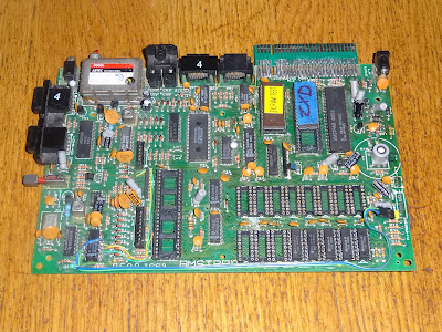
Looking at the board, it appears the Z80 and ROM chip have been replaced in the past.

Based on the unmistakable smell of 80s flux, I would have thought this happened sometime in the 80s when the machine was only a few years old - the rest of the chips seem to have matching late 1983 / early 1984 date codes.

I start by desoldering the Z80. Please only do this if you have experience with this sort of thing. It is very easy to damage these boards, lift tracks and pull out through hole plating etc. so please be careful and use lots of flux and lots of time, and if in doubt, don't.

Nice clean removal, no damage caused by me (or the person that originally removed the Z80).

Time for a new one. An RS bagged one no less. (actually, I can tell you a trade secret here, since they no longer sell them. Because RS, their pricing was a bit off, and it worked out cheaper to buy bags full of the individual bagged Z80s instead of buying them in a tube. This makes no sense, but I have spent many happy evenings in front of YouTube "shelling" Z80s and putting them back into tubes)

I notice it says PEC on the bag, but PEG on the chip. Not sure, but I think PEC is not ROSH and PEG is the later lead free version?

Anyway, old Z80, new Z80. Lets get it fitted.

I like to use a socket, in the unlikely case this doesn't fix the issue, I can put the original back.

All nice and neat.

Checking the M1 pin now, it looks a lot better.

The M1 line is now doing stuff as it should, all nice and clean sharp transitions. The number of clock cycles per instruction varies, so the mark space will not be consistent, however, it will always be clearly 0 or 1.

Time to give it a go, and well, of course it worked.
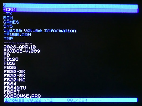
Ah, that's what I was looking for.

I love a bit of Spellbound. It's a hard life having to test these things....

So there we are, another Z80 with a bad M1 line found and replaced and a working ZX Spectrum and divMMC ready to go back.

I've cut out a bit of a long and ranty bit about "refurbished" computers here, go to Patreon if you want to see the original version.
By the way, if you have read this far, please give the post on Twitter a like and/or comment, and consider subscribing to the Patreon if you want to read more of these. Check back here every Sunday for a new post.
Anyway, it all seems to be working, ready to go back.

Advertisements
DivMMC Future
The DivMMC Future is available from The Future Was 8 bit. Don't worry if it shows as "backorder", more are currently being built and should be shipping this week.

Patreon
You can support me via Patreon, and get access to advance previews of posts like this and behind the scenes updates. These are often in more detail than I can fit in here, and some of these posts contain bits from several Patreon posts. This also includes access to my Patreon only Discord server for even more regular updates.