Sunday, 19 July 2020

Mini PET Update

This is an old post, preserved for reference.
The products and services mentioned within are no longer available.

The Mini PET seems to have been received well. I am seeing lots of pictures of very neatly assembled boards (and also the one that TFW8b built) and revived PETs up and running again.
That's great to see, and very few problems building them, other than a few people who had to built it without reference to the manual (the person packing the orders has of course been fired). So far, the only issue to report is a slight error that seems to have slipped though all of our other testers (who have, of course, all now been fired).
When first putting together the design for the prototypes of the Mini PET, I came to the userport and was pleased to find I had already drawn a component for the PET userport. Perfect I thought and added it to the design. I didn't consider at the time that I had drawn that component for things which plug into the userport on a PET, not for the host side of the PET userport, which is the mirror of that pinout. (I have, of course, also been fired)
And so, the pinout is reversed. Pins that should be 1,2,3,4... are 12,11,10,9... During testing, no one it seems noticed that, as no one it seems has anything that would plug into the PET userport. The only things I had were userport sounders and composite video output. All of which were already provided on the Mini PET. I think this will only affect a handful of people making userport serial interfaces, as the PET seems to have hardly any commercial userport peripherals.
I have made some boards which reverse the pinout. An interesting routing problem, 12 wires what all need to cross over each other and the same on the other side of the board.
I'm fairly happy with the solution I came up with, although I wonder if there is a neater way to reverse the connections? Those are being sent out to anyone with an affected board (V1.42, V1.44), although no one has actually asked for one, and only one user has reported a problem. The ones going out have white soldermask.
I build a little LED tester plug to make sure that was working correctly.
Because of the userport problem, I have moved more quickly than planned to the next board designs, as correcting the pinout on the userport required quite a bit of rerouting. The updated versions of the 'Kit A' boards is V1.45.
Other than the correction to the userport pinout, and a couple of minor tweaks, this is pretty much the same as before.
The LED tester confirms the pinout on these boards is now correct, so the twister boards are not required for V1.45 and later boards. The new 'kit A' versions (for use stand alone with a keyboard) are shipping now.
The Mini PET boards had been designed to be the same size as the keyboard PCB, which had already been designed as a direct replacement for the chiclet keyboard on the 2001 PET, so the Mini PET was designed to be the same width as that.
That meant it wasn't quite wide enough to pick up on the two mounting pillars at the back of the PET case.
I had tried out a green soldermask version of the Mini PET board and that had looked better inside the PET case. It seemed a good opportunity to split this into two versions, one white soldermask board, the same size as the keyboard, for stand alone use, Kit A. The second, a green soldermask board which fits inside the PET, kit B.
The first thing to do was to make the B boards larger, so they are now the same width as the top end of the original PET boards.
So those now fit into the case and pick up on both rear mounting pillars.
It also seems a good idea to remove things not required for this version.
I've removed the DC jack, and boxed off the composite video section, which can be fitted if you need it, but otherwise can be left unpopulated.
You can see here I prefer to fit the smaller logic chips without sockets. They are still supplied in the kits if you want to use them, I just think it looks better without. TI uses the same moulding for 14 and 16 pin chips, so when aligned correctly, you don't see the difference between 14 pin and 16 pin chips.
The wider kit B boards now pick up on both rear mounting pillars, and the power supply interface board has been integrated to make a single board solution.
As before, this can be used with the 9 way power connector found in most PETs or the 5 way connector from the original 2001s. You could cut down the pin header before soldering if you are only going to be using the 5 pin connector. But it's not a problem if you don't, one missing pin is an extra ground, the other two are for a second transformer winding which is not used.  
There is now a side datasette port, for datasette 2, positioned as on later PETs, so the board gives access to both rear and side datasette ports.
This now works better for the 8032-SK case where the board is mounted at 90 degrees, and the side port becomes the rear port.
The board picks up on the same two mounting points and the extension cables connect as normal inside the 8032-SK case.
The board can alternatively be mounted further into the PET case, which allows an SD2PET to be installed inside the case. This can be useful in unattended events to keep it away from prying hands, or for those short of desk space, or wanting to access the SD card by lifting the case rather than reaching around the back.
The second datasette is still accessible through the holes in the case in this configuration.
You will see I have moved over to using jumper settings, rather than DIP switches on the B boards (thinking it would be adjusted less frequently once mounted inside a PET case). 
I'm not sure about this, and may go to a single 8 way DIP switch on future boards as it adds quite a few extra parts to be sorted out and soldered in, but keep the onboard labelling of options.
These kits are being distributed by The Future Was 8 bit. My Tindie store remains closed due to the ongoing problems with shipping. 

2022 Update: The Mini PET has been replaced by the Mini PET 40/80. This has a built in much nicer keyboard and supports 40 and 80 column mode. Also available is the Mini PET 40/80D, a preassembled drop in replacement board with a built in SD2PET. Both are available now from The Future Was 8 bit.

Sunday, 28 June 2020

Mini PET Options

This is an old post, preserved for reference.
The products and services mentioned within are no longer available.

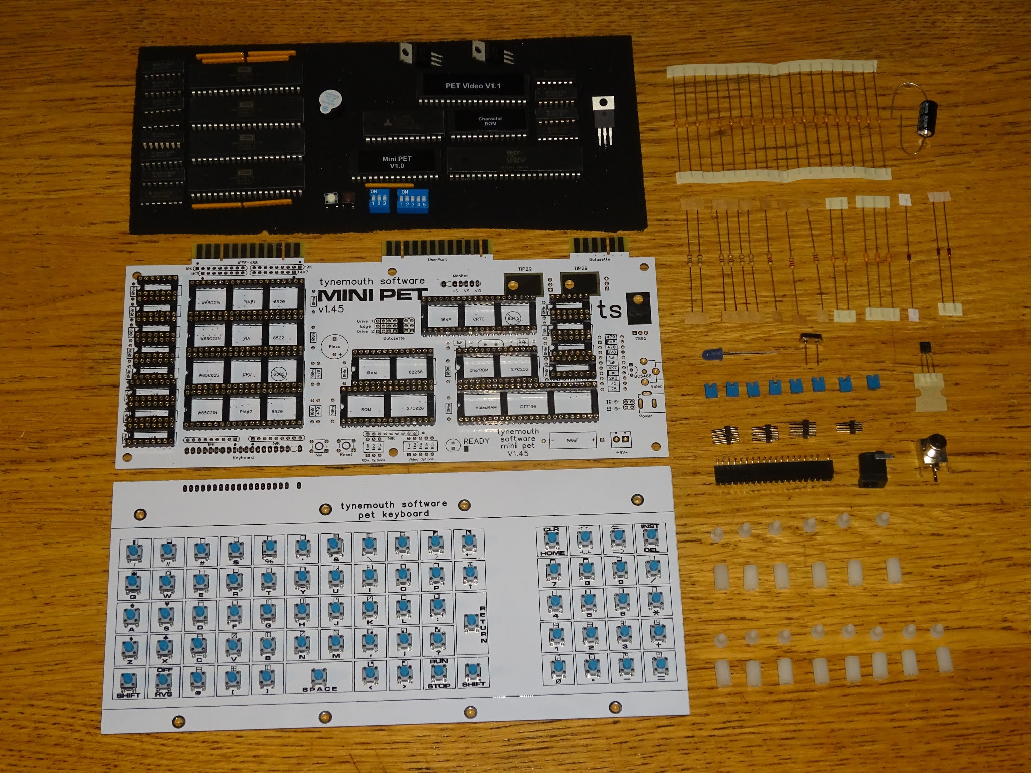
As I am starting to put together the kits for the second batch of Mini PET boards, I thought it would be useful to go through the options available.
All versions share the same main board. This provides the following:
  • W65C02S CPU running at 1MHz
  • 32K RAM
  • 20K BASIC / OS, 2x4K option ROMs
    • Original BASIC 1/2/4
    • Custom Mini PET BASIC 4
    • Built in ROM/RAM self test
  • Compatible with most Commodore PET software and peripherals, with the following exceptions:
    • The screen is 40 columns only, so any 80 column (mainly business) software will not look correct on any 40 column PET
    • There is no CRTC chip, so any software (mainly later demos) that needs a CRTC will not work
    • The CPU socket is not pin compatible with the original NMOS 6502, so nothing that plugged into the 6502 socket will work.
    • There are no internal power headers (but these were generally only used in conjunction with the CPU socket above). 
  • 2x W65C21N and 1x W65C22N providing the following IO ports
    • IEEE-488 bus for disk drives / printers
    • Userport with 8 bit parallel port
    • 8x10 keyboard matrix
    • 2x Commodore Datasette connectors (compatible with C2N and 1530)
    • Piezo sounder connected to CB2 (as required by Invaders and as fitted to later PETs)
  • 1K video RAM providing 40x25 character based display, via one of the following:
    • Composite video, monochrome PAL / NTSC
    • PET 9" monitor
    • PET 12" monitor
  • Single 9V DC supply from external supply or PET transformer, 170mA 
  • Self assembly kits. 
    • Modest soldering skills are required. 
    • All through hole parts.
    • All brand new and currently in production.

Kit A - Standalone 

This is the version of the Mini PET which is stand alone PET compatible computer with it's own keyboard. This would normally be used with a 9V DC power supply and would drive a composite video TV or monitor.
This goes well with an SD2PET future SD card disk drive.
The keyboard is connected underneath the board via a 20 way 0.1" header, and can be detached for easier storage. 
The combined unit stands on a number of nylon pillars, which are M3 threaded if you wish to attach to a baseplate.

Kit B - PET Replacement Board

This version would normally be used to replace the mainboard in a Commodore PET case. It should fit in most cases from the 2001 to the 8096-SK.
If mounted at the back of the case, the three edge connectors line up with the holes in the case where the orignal PET board had it's edge connectors.
The board is much smaller, so only picks up on one mounting post, at the top right. The rest of the board is supported on self adhesive pillars.
Power is taken from the PETs power transformer using a power interface board. This makes use of the large capacitor in the case in the same was as the PET mainboard did. The output is a single 9V DC supply for the Mini PET board.The blue wires are a second winding that used to feed the 12V supply. This is not used.
The PET 2001 also only required 9V in, so did not have the extra windings, and used a 5 way plug rather than  9 way, this should be aligned to the edge, where the brown, red and black wires line up. The connector is symetrical, so either brown wire can be towards the edge.
The 9V plugs into the Mini PET board, as do the PETs keyboard and monitor. The Mini PET can drive a variety of monitors, with appropriate DIP switch settings.
The black and white 9" tube on the original 2001s.
The green screen 9" on the 2001N/30xx/40xx series.
The green screen 12" on later 40xx and 80xx models.
The Mini PET can support both the graphics keyboard (top, found in most 2001/2001N/30xx/400xx PETs) and the business keyboard (found in 4032B and 80xx machines). Although most software was written for the graphics keyboard and some games may have hard coded keyboard scanning routines rather than using the OS ones, so there may be some issues with certain programs.
Another option for mounting is to move the board further into the case, so an SD2PET future can be installed inside the case. This is useful if you need the space behind the PET, or don't want the extenal device to be visible (or where it may get borrowed).
The datasette board can be used to still have an external datasette power at the rear or side (or the internal drive on a 2001)
You can also fit the board inside an 8032-SK case, and use the original cabling to feed the front and rear connectors.
Or disconnect the external IEEE-488 port and fit an SD2PET future inside.

Various options there, available to order now from The Future Was 8 bit. What are you going to do with your Mini PET?

2022 Update: The Mini PET has been replaced by the Mini PET 40/80. This has a built in much nicer keyboard and supports 40 and 80 column mode. Also available is the Mini PET 40/80D, a preassembled drop in replacement board with a built in SD2PET. Both are available now from The Future Was 8 bit.

Sunday, 21 June 2020

IKA Logic SQ200 Logic Analyser Review


This is a new toy I have just got, I've only had it a few days, but I've been quite impressed so far. It is an SQ200 from IKA logic, a 200MHz 4 channel logic analyser / signal generator.

I've been using a DSLogic Pro for the last three or four years, until last month it stopped being detected properly. It is one of those things which has the firmware loaded onto it by the driver, so it connects as one type of device, get the firmware, disconnects and then reconnects as the proper device. That has stopped happening now, and I've not been able to get it to identify properly, so it's bricked, currently waiting to hear back from support to see if there is anything they can do.

In the interim, I have been using a cheaper generic clone of something or other from ebay. It works, but has a sample rate of 24Mhz, which means it's not accurate enough to things changing at 16Mhz. I am currently working on the firmware for the Mini PET video controller, and the timing has to be precise down to one instruction of it's 16Mhz clock, and that is down in the sample noise of that unit.

So, time to get something that's a lot faster. This is 200Mhz, so is rather to be able to cope with signals up to 50Mhz, which is more than enough for what I need at the moment. It's limited to four channels, which is not ideal for some of the other things I do where 16 or more would be useful. But for serial protocols like UART, I2C, SPI etc. and the current video signalling it's great.

The unit comes with a USB lead and some probes. It's a very small box, 50mm square, but I guess it doesn't need to be any larger.

I wasn't too impressed with the quality of the supplied probes, those sort of clips aren't very good with IC legs. The connector at the device end is just a 5 way 0.1" connector, which is great, so you can make up your own leads. Not sure how that will work out with the higher frequency signals, but I guess just keep the leads short.

I have made up a set using the EZ Hook clips I have been using, these were a bit expensive, but have been worth it.

Because it is a easy connector to use, I have also made up a custom lead for the current job so I don’t need to clip multiple probes on each time.

The software is custom, and it is not currently supported by the open source sigrok Pulseview programs I have been using. So far it seems very nice and is doing what I need.

At 200Mhz I can capture 20mS, which is enough for a frame of video, and I can zoom down to line and pixel detail.

The issue I am currently dealing with is based on timing of the HSync pulses. They should all be 24uS high followed by 40uS low, but somewhere there is one that is slightly out. The dot clock on the PET video is 8MHz, so each pixel is 125nS wide. 
One instruction cycle on the microcontoller is 62.5nS, so a couple of instructions out and you are one pixel to the right of where you should be. Most of the code is NOP instructions so there are only a couple of NOPs to move around to fix it.

Various tweaks to the timing have given me close to the correct result, but each of the video modes needs to be dialled in to the exact timing. Ah, there's one of the culprits that 40us pulse is 60nS longer that it should be. One NOP instruction removed and it's now 40.000uS.

That is enough to change the video output from...

...to

A nice straight line, and with all the other timing tweaks, composite and drive to CRT monitors is now all working nicely with nice straight edges on the side.

The SQ200 has a lot of functionality I have yet to investigate fully. One thing that looks very handy is being able to set a conditional trigger, only trigger when that signal is low and that one goes high, then low before the other one goes high, and things like that.

It had protocol decoders built in, so you can decode I2C etc.

It can work as a signal generator, and can also work as mixed input and output, so it can actually send I2C commands and display the results.

So that's looking like a very handy tool to have, and helped me finish off the last few tweaks to the PET video firmware.