Wednesday, 16 March 2016

3D Printed Raspberry Pi Cases

I've been working on an installation of several of my retro PC USB keyboard with Raspberry Pi, running various old computer games for a museum exhibit. The original idea was to use the ZX Spectrum Pi Zero, but there were maybe a few too many wires that could be unplugged etc.
The revised plan was to use separate ZX Spectrum USB keyboards and mount the Raspberry Pi's behind the scenes. I had a look around for suitable wall mounting Raspberry Pi cases, but was surprised to see there weren't many around.
I did consider adapting some ZX Power Supplies for the purpose. It would be in keeping with being plugged into the Spectrum keyboards, and they were just about a perfect size, maybe a bit high. However these wouldn't been seen and there were going to be initially 3 of these, plus a spare, so that would have been quite a lot of holes to cut out.
A fried of mine found some 3D models on Thingiverse, Credit to the original designer these were very nice cases. The lid was a bit busy with cutouts for vents, camera, monitor, GPIO etc. so he respun the design to have a plain lid, then added the 'ts' tynemouth software logo to give a bit of ventilation (see his write up of using Fusion 360 for this). He then 3D printed the cases for me.
The mounting holes are on 100mm and 75mm squares, so are VESA compatible if you wanted to mount one on the 4 screw holes on the back of a monitor. These looked great with the activity lights shining through the clear cases.
The Spectrum and Commodore 64 emulators run fine on the Pi Zero, so I used the single core Raspberry Pi B+ for the other units to share the same microSD card images.
Later a 1990's PC game was added to the exhibit which needed a bit more power to emulate, so I used a Pi 2. I did try the Pi 3, but in this situation the onboard wifi was a disadvantage, and the extra speed didn't make a noticeable difference.
The Pi 2 cases were printed in blue to distinguish them from the Pi B+ ones. It is the same 3D model, there is enough space and vents on the base of the case for cooling of the extra chips on the 2. This was purely to make sure the units didn't get mixed up.

Monday, 14 March 2016

Zipstik Joystick Repair

This is an old post, preserved for reference.
The products and services mentioned within are no longer available.

The Zipstik has always been a favourite joystick of mine, a nice simple four way stick with two fire buttons. It has a very good action due to using microswitches throughout, giving a solid click when you move or fire. A bit like the clicking of the IBM Model M keyboard I am typing this on.
I've use these a lot when testing my USB joystick adapters, and the USB joystick options on C64 USB keyboards, as well as of course on original machines from the 1980s.
These use the standard 9 way D pinout common to machines from the 2600 through the C64 and VIC20 to the ST and Amiga, but not the Spectrum +2 (thanks Amstrad for changing the pinout).
Most of these are pretty solid, but I picked one up recently that wouldn't move up. It didn't click when moved up, so was probably the switch at fault, which I verified by shorting the contacts on the up switch and it moved up.
The microswitch is a standard size and shape, and has been used since at least the 1970s on various devices, and is still available today. There are various options for force and actuator and connection types. Most have common, normally open and normally closed contacts. The ones in this joystick only needed common and normally open, the extra tag can just be ignored.
In order to maintain a uniform feel, I opted to replace all four direction microswitches. The two fire buttons were different type, with a blue edge. These worked fine, so I left those in place.
This particular Zipstik had an autofire option. Like many autofire circuits of the era, it was intermittent at best, and support varied from machine to machine. This one didn't need 5V, and just connected from ground to the fire line, This was soldered to the tabs, rather than being crimped it. With no separate power connection, it was drawing power from the pullup, so it wouldn't work on things like a Kempston joystick interface for a Spectrum where the common is actually 5V and the signal lines are pulled down to 0V. In this case I opted to remove it to simplify things.
The new microswitches I have used are Cherry D45Y, these are rated for 100,000 operations, so should last a while. These are high current versions, which I think have a more solid click than the low current ones that could have been used. These have larger spade connectors than the originals, but since some of the original connectors have been soldered to, and some are frayed, I replaced all the crimps with larger larger ones. With the removal of the autofire, the ground wiring was rejigged slightly, so I made a new ground connection for most of the switches, all chained together.
After the case had a cosmetic cleanup, time to reassemble and test. Here I'm using my old faithful joystick tester - just a battery and some LEDs in a box wired to a 9 way D connector, but quite handy for quick testing like this.
That's all working, it's first task is with one of the USB joystick adapters, configuring RetroPi on a Raspberry Pi 3.

Thursday, 25 February 2016

Commodore 64 Pseudo Stereo Dual SID Questions

This is an old post, preserved for reference.
The products and services mentioned within are no longer available.

Just a quick update on the Commodore 64 Psuedo Stereo Dual SID boards, see the previous article for more info and the buy it now links. This is to answer a selection of questions along the lines of 'will it work with...'.

Will it work in a Commodore 128?

Yes, it will. The Commodore 128 has a 6581 or 8580, driven in a similar way to a Commodore 64. When ordering, go for the normal height (i.e. raised up by one socket height) version.
The C128 does have a metal shield which will no longer fit if the board is installed, so you would need to cut out a section, or remove it. If you remove it, may be an idea to fit heatsinks on some of the chips which use to sink to the metal cover. The C128D and DCR should both be fine, as long as there is space enough for the board to fit.
Power isn't as easy to tap as the C64, the best place I found was on pin 1 of the 7812 regulator. Be careful when clipping on there to avoid touching the centre pin. Maybe add a drop of hot melt glue or bluetak to hold it in place and away from the other pins.

Will it work with a Commodore 64 Reloaded?

Sort of. The power input to the Reloaded boards is 12V. This is filtered and fed to the SID, or can be fed via a 3V zener diode to give 9V for an 8581 SID. The normal dual SID boards have onboard voltage regulators to generate 9V and / or 12V for an unregulated DC of 15V or more, which is present inside the original Commodore machines.
This will need a special build of the dual SID board without the regulators. There is a jumper on the Reloaded board which shorts out the 3V zener to select 9V or 12V. I think I can remove the jumper and connect a 2 wire lead there to tap off the 12V and 9V. This is currently untested, but it should work.

Will it work with a Nano SwinSID?

Yes. The Nano SwinSID can be used, but with a few caveats. Firstly, the board is a bit higher than a standard SID, so will cause height issues in a C64C. I could solder the Nano SwinSID directly to the board and reduce the height if required.
The sound level output seems to be lower than a normal SID, so bear that in mind; you may need to adjust the levels on whatever you connect to.

Can it be used as dual individual SIDs?

Yes. The default setting is both SIDs are fed the same inputs and generate pseudo stereo effect. But, remove the CS#2 jumper and connect to one of the decoded IO lines on the cartridge port and if your software supports it, you can drive the two SID independently.

If you have any further questions, let me know, or see the previous article for more info and the buy it now links.

Thursday, 11 February 2016

IBM Model M Keyboard Restoration

This is an old post, preserved for reference.
The products and services mentioned within are no longer available.

I've been asked a few times recently about the IBM Model M keyboard I use, so here are some photos I took when I restored it. I use this daily as my main keyboard, seen here with my other favourite and slightly out of date input device, the Microsoft Wheel Mouse Optical. I'd be very reluctant to change either of those.
It looks very nice now, almost like new, but that's not how it looked when it arrived. It wasn't a very promising start, but it appeared basically intact. There was one key missing (the number 1 on the top row), and no cable - the cable on the Model M was detachable, and this one had been detached and lost or sold separately. It also needed a serious clean. You could probably work out the previous owners password from looking at the clean keys.
I stripped it down to clean it and looked around for the missing parts. I found a cable, but when I tried the keyboard, it didn't work. It powered on correctly, the caps lock, scroll lock and num lock LEDs flashed on, and then off, and they could be toggled using the appropriate keys, so all looked promising. However, as soon as the PC booted, it stopped responding, the LEDs no longer changed and nothing was sent to the PC. I checked continuity and the cable was fine, so I suspect this was due to the 7406 buffer on either the clock or data line.
I did considered making a USB keyboard controller to fit in place of this board. Before I got around to fixing or replacing it, a second Model M arrived. I had found this one when looking for replacement keys. This one had been described as incomplete, not working and for parts. It was missing several keys, the cable and the screws. I guessed it was the remaining bits after someone had made one good keyboard out of bits of two.
I don't know how bad it was before it was posted, but it was much worse when it got here. It arrived worse for wear, having been badly packed and then thrown about by the courier. Many of the keys were loose in the bottom, and some had fallen out of gaps in the box, thankfully the one keycap I needed was still present. If the seller had actually put the keyboard on one of these bags I might not have lost the keycaps. I don't think anyone would package one like this today, at 5p per bag, there was about £1 worth of bags in there.
When I tested it, not all the keys worked, but most did, so I could conclude the controller board was probably OK. The problem in this case was due to the Achilles heel of the Model M, the plastic rivets that hold the backplate on. These can snap off, and many had, maybe made worse in transit. These are worth repairing, you drill them out and bolt the two halves together. Some of the springs were damaged or missing, so it's going need a bit of work.
However, I now had a working controller and a full set of key caps. Putting those together with the original keyboard and the cable, I had enough bits for a complete keyboard. Time to put it back together.
The model M has quite a unique construction, and is what makes it such a nice keyboard to type on. The keys use a buckling spring, when the key is pressed down so far, the spring buckles and forces down the plunger onto the membrane below, giving clear tactile feedback and making a clicking sound. The sort of haptics they try to recreate today on touchscreens. Yes, it is just a membrane keyboard, but the springs are the secret of it's success.
Most of the keys are an unusual two part construction, a blank key with a little cap that clips over the top. I suppose that made it easier to product regional variations? The larger keys are solid parts, with either have a dummy plunger on one side (the white insert on the bottom left), or a metal bar support (fitting into the green clips on the right).
Having restored many types of keyboard over the years, these bars are often used on space bars and can be very fiddly to fit. These ones just slide in really easily, a very nice design. This one had metal bars on the Enter key, and the numeric keypad + and Enter. The second keyboard was the same, but the keycap for numeric keypad enter it came with didn't have a bar, that seems to have come from a third keyboard which had the white insert on Enter, like on the 0 key. This supports the previous assumption it was the bits left over from a merger.
The white key in the centre of the numeric keypad may look wrong, and I initially thought it was, and was going to replace it was a grey one from the other keyboard. But I think it is meant to be like that. The F and J keys are also white. These are the three keys that have a slightly raised bar at the bottom of the keycap to aid locating your fingers when touch typing. These are also useful when putting back the keycaps as you can locate the key in relation to F or J rather than having to count from the edges.
With all the keys replaced, the keyboard slides into the base board. Nice solid plastic, just needed a good clean. The controller fits into a slot in the base, the with the LED board and earth strap connected to it. Earth strap! how many keyboards these days have an earth strap, or indeed a large lump of metal that would need earthing. They really don't make them like this any more.
The cover, again, just needed a good clean. It bolts together with unusual hex head bolts, a bit like the original IBM PC.
Finally clip in the keyboard cable, coiled of course. These came in various versions, an RJ45 for some industrial terminals, I think there was a 5 pin DIN for older computers, but this would have come with an IBM PS/2 computer. That range of computers introduced the new 6 pin mini DIN PS/2 keyboard and mouse connectors. These are still used today, there is still a PS/2 port on my main PC, even though it was built more than a quarter of a century after the keyboard.
The same is true of the keyboard layout. This keyboard introduced what is still pretty much the standard layout today. The only thing missing is the Windows key, which was slotted in between Ctrl and Alt later on. Other than that, the mapping is exactly as it should be. I have the right Alt key (marked Alt Gr here) mapped as the Windows key, as I use shortcuts like Windows + E to open explorer, Windows + L to lock the screen etc. I've also got the Pause/Break key mapped as the pause button on my mp3 player (good old Winamp).
The only anomaly I have found is the key on the top left is labelled `¬| and the key between Z and Shift is marked .  On a modern keyboard they would be `¬¦ and \| . It seems the pipe and broken bar ( | and ¦ ) have changed place at some point. The keys act as you would expect on a modern keyboard, shift \ gives | which is fine by me. The pipe character | is used in many programming languages and on the linux command line.
I'm not sure I've ever used the broken bar ¦ other than in writing this paragraph. I suppose you could use it to make an ASCII art picture of the strain relief on a DIN plug |¦|¦|¦|¦| ? In case you were wondering, hold down right Alt (Alt Gr) or Ctrl and Alt together and press the top left key. You know, the one above tab with the wrong apostrophe ( ` ) and the weird line with a bit at the end ( ¬ ) that I think is meant to be 'not', although tilde (~) is more often used. OK, you can now forget about that key again.
There is a date code on the back, 21-09-1988. I have friends who weren't born when this keyboard was built and now have kids of their own. All in all, a great keyboard. It wipes the floor with modern soft membrane keyboards, and stands up well to modern mechanical gaming keyboards. I do have just about enough bits to make up the second one, once I fix the controller and replace the plastic rivets. I'm sure I'll get around to that one day as these are such nice keyboards to use, I wouldn't change it.

Update:
The donor is now also back up and running, I ordered the missing keys and cable from a website in the US (clickykeyboards.com)

Monday, 8 February 2016

VIC20 Penultimate Cartridge Part 3 - No more DIP switches

In the last post on the VIC20 Penultimate Cartridge I am currently working on, I expanded the ROM and RAM capabilities, but at the cost of increasing complexity. There were now 9 DIP switches (soon to be 10), 4 to select the ROM and RAM mode, and the rest to select a ROM image set. This came with a long table of the ROM and RAM setting required for each ROM set. For example, you would need to set mode 1 and ROM image 0 for Avenger, and mode 9 and ROM image 8 for the diagnostics cart etc. This worked fine, but would be a bit annoying to use, keep having to refer back to the settings list, which was too large to print on the cartridge case.
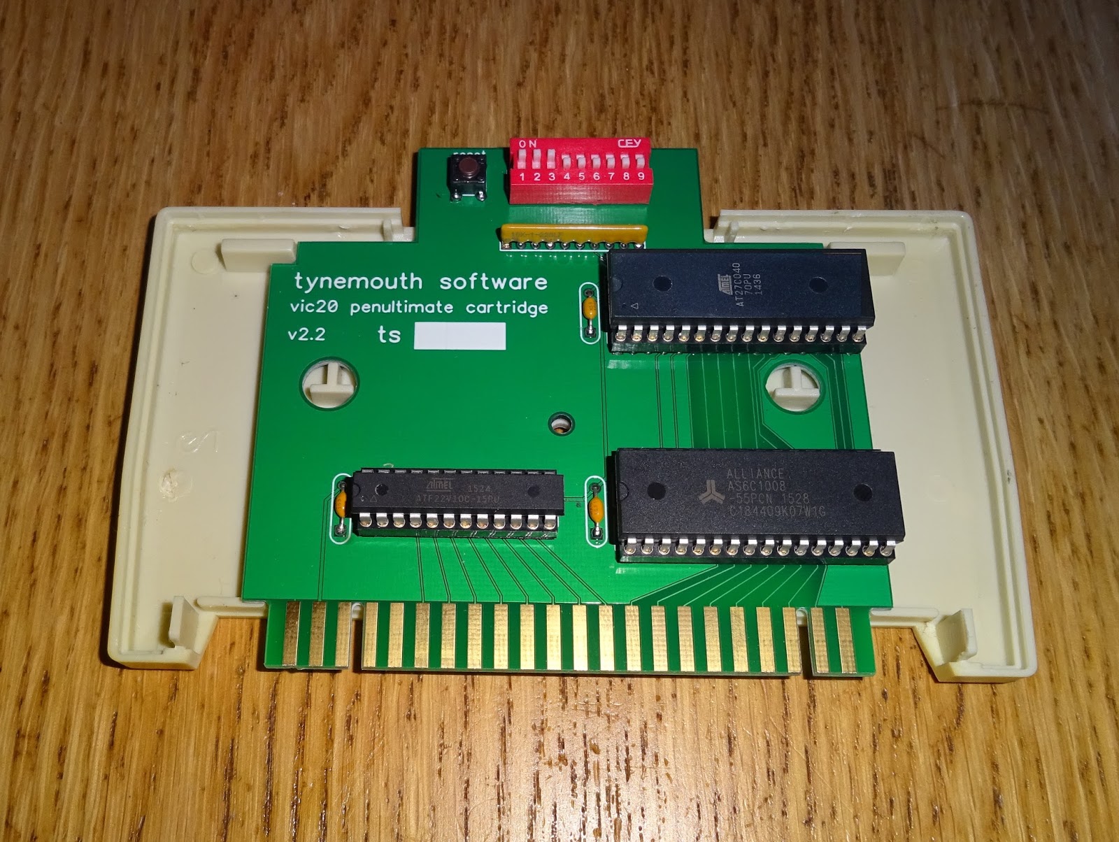
To make this easier I wanted to automate the switching, using a menu program on the VIC20 to the set the mode and ROM image, and then reset itself to start the selected ROM. I started looking at the options for this and designed a new version of the board. It started to get complicated quickly with multiple latches to hold the mode, and the ROM address, and also something to generate a delayed reset pulse. There was also the issue of getting it into a start mode.

To simplify things, I went for a microcontroller, this would do all the latching, and generate the reset pulse. It could have a set starting state, and also would allow the mode and address to be preset, but not changed until the reset pulse, so as not to mess up the menu code which was currently running. This was fitted dead bug style on one of the previous boards, to test this out properly. The LEDs show the ROM/RAM mode being set. The cable at the top is connected to a programming header, from a bit of another board glued onto this one.

The VIC20 has some helpfully address decoded signals on the cartridge connection, for IO chips. I found when testing this, that just triggering on the IO2 signal was a problem. It seems the normal operation of the OS reads from addresses in the IO2 range at about 60Hz, so I used some spare gates in the GAL chip to generate an IO2 and write signal to trigger the latches.

I've added an LED bargraph for testing, I don't think the final version needs that, as much as I like flashing LEDs, it's not really necessary. With the additional write gated IO2 logic, and the microcontroller code written, the LEDs were all being set correctly. The idea of operation would be as follows, when the VIC20 is powered on, a default mode is selected which runs a menu program from ROM. The menu will have a choice of options, all of which will lead to setting the mode and ROM address and resetting the VIC20. When the VIC20 resets, the selected game or whatever will run. There is a button on the cartridge which when pressed will bring the menu back up. It does this by resetting the VIC20 and setting the mode back to the initial state - the mode changes happen whilst reset is held down so it is never in an inconsistent state.

I've setup 4 commands:

  • POKE 38928,X - change to mode X imediately
  • POKE 38929,X - change to ROM address X imediately
  • POKE 38930,X - change to mode X, apply pending ROM change and reset
  • POKE 38931,X - preset ROM address for above

This should cover most of the options required. The menu should be able to offer things like

  • Run a game cartridge from ROM (8K/16K/Atari 16K/Scott Adams 16K)
  • Run the VIC20 diagnostics software (which needs ROM and RAM)
  • Run Super Expander or other BASIC with up to 27K RAM
  • Exit to BASIC with 3K-35K RAM

But also I think I should be able to get it to run some commands on reset

  • Exit to BASIC with 3K-35K of RAM and execute LOAD "*",8
  • Exit to BASIC with 11K-35K of RAM and execute LOAD "FB20-8K",8
  • Select a Scott Adams adventure and execute SYS 32592

Being able to autostart a diskimage or the file browser on an SD2IEC (or a 1541 if you like), would be a nice feature to have, and avoiding typing SYS 32592 makes the Scott Adams adventures easier to use.

The new board is now designed and ordered, and will still fit in an original cartridge case. Whilst I'm waiting for those to arrive, I need to write the menu program.

There has been a lot of interest so far, I think this has the potential to be a very useful product. I'm thinking in future I could remove the large (and expensive) EPROM and use a larger micrcontroller to load the ROM images into RAM from a small serial EEPROM. The whole thing could then go surface mount and once the board is smaller, maybe even a custom cartridge case....

Update:

The new boards are here, the software is taking a bit longer to write.

My VIC-20 coding is a bit rusty. I have a very basic BASIC version, but I am looking to write a better version in C.

Update 2:

I have some simple single ROM cartridge PCBs, if you only want to replace a single game.

If you like DIP switches, I still have some of the current version of the PCB available, built and tested with up to 35K RAM and 32 ROM images:

Update 3:

The menu software has been rewritten in C.

Initial testing is underway, so far, so good.

Update 4

Penultimate Cartridge V4.3 available now, all menu driven, no DIP switches.

Penultimate Update:

The production version of the Penultimate Cartridge is now available from The Future Was 8 bit