Saturday, 30 April 2016

PET Diagnostics - Upcoming Project Preview

This is an old post, preserved for reference.
The products and services mentioned within are no longer available.

This is a preview of an upcoming project. Not sure if the name will stick, but at the moment it's called PET Exerciser (UPDATE: it didn't, it's now called 6502 Diagnostics). This started when I was repairing a few PETs and was using a NOP generator. This idea of these is the hard wire the NOP instruction onto the processor databus, the end result of that is it just steps through all the addresses sequentially, continually. That is useful to check address decoding, and see if chip enable pins are pulsing in the right way. The trouble is the 1MHz 6502 based NOP generator is a bit slow to check high address bits on a scope (at least one without digital storage), but too fast to check by eye.
I got to thinking, could I adjust the clock rate fed to the 6502 to get the pulses into a more usable range? Before I started looking at that, I thought that it would be easier to just bypass the 6502 all together and use a couple of 8 bit counters to cycle through all the address bus at whatever speed I chose. I did look at a few options for that, but it was going to be a bit messy as it would have ended up with 4 x 4 bit counters and a pulse generator, which was maybe going to be an 8 pin microcontroller. I then thought I could just use a microcontroller. And lo the PET exerciser diagnostics was born.
I then got to thinking, if I had a few more pins on the microcontroller, I could access the databus and some of the control signals as well. Hmm. interesting. The prototype doesn't look as neat as that final PCB will.
Under that mass of wires is a Commodore PET, and on the breadboard is a micrcontroller, the DIP version of the one I will use on the final board. The microcontroller is connected to most of the pins in the 6502 socket. There isn't an actual 6502 involved any more. Before I got around to writing the code for the NOP generator. I was interested to see if I could actually drive the PET hardware to do anything interesting.
This is the first test was a screen of incrementing characters, but as I got the hang of writing the PET video RAM, that quickly grew into a character table. If nothing else than to help me work out what characters to write the the video RAM to show on the screen - it's PETSCII, not ASCII. Since I can now write to RAM, I can also poke things, and one useful poke on the PET is to change character sets from business mode (with uppercase and lowercase letters) to graphics mode (without lowercase but more symbols. This sets CA2 on the VIA which controls the high address line on the character ROM.
Here you can see the PET board I was testing has a faulty character ROM, some of the symbols are not displaying correctly in graphics mode. OK, this is proving rather interesting and should be very useful. What next? Well, let's test the RAM. I'm currently working on a 2001 board, so I've only set it to test the first 8K. I've split it into 1K blocks and tested by bit to help narrow down the faults.
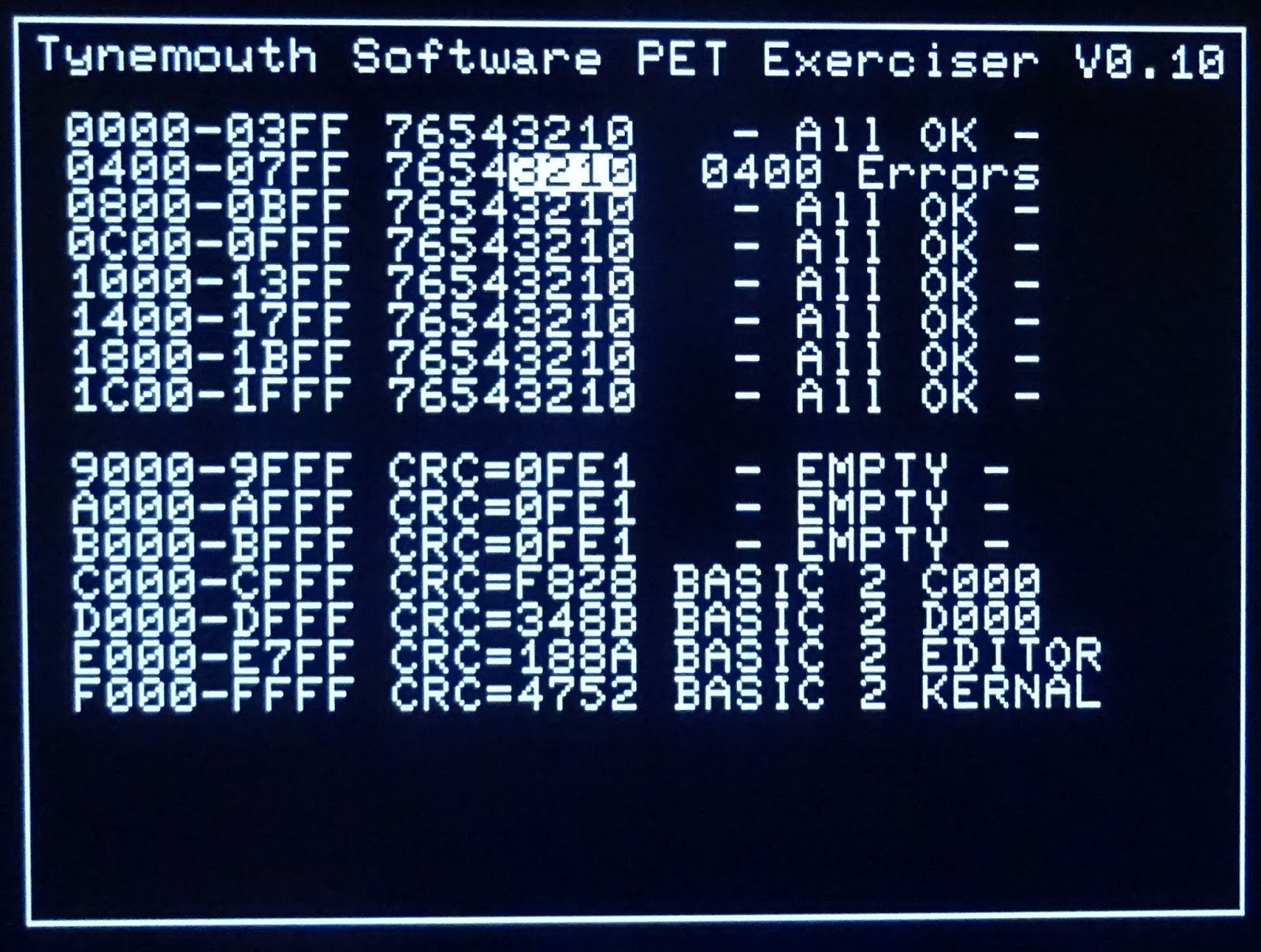
The test algorithm I'm using is fairly simple, I'm just poking various values and reading back. I'm recording any bits that are different from the values written, and here it has picked up 2 errors on one RAM chip. This matches what BASIC was showing when the PET was running, it only detected the first 1K of RAM, so was showing around 800 bytes free. I've removed the chip I think it is, and retested.
Good, it's showing 400 errors (that's 400 hex, 1024 decimal), all in the lower nibble, which is exactly the area served by the 2114 chip removed. I tried to lay the screen out to match the orientation of the chips, so the second row of 2114 chips, right hand side is the culprit.
I replaced the chip and retested and it's now fine, and when I return this to 6502 control, it should detect all 8K of RAM again. The TMS2114L-20NL I have used there isn't an exact replacement for the TMS4045-45NL, but is enough to prove the point whilst I try to locate something better. I'll probably use one of the pair that are the video RAM, and replace both of those with faster 2114 chips.
You can see where I was also starting to test the ROMs. I've gone for a simple 16 bit checksum of the ROMs, and that seems to be working consistently. I've added a lookup table of CRC codes with descriptions for known good ROMs. I've got it plugged into one of my 6502 ROM/RAM boards for testing, so I have been able to get CRCs for most of the standard ROM sets already. This is a good way to identify faulty ROMs.
Here some of the 6540 ROM chips are working (I've given the chip numbers of the good ones), but the others are coming back with different CRCs. The CRCs have also changed on those as I have repeated the test, so I guess they are faulty, or since it is only the x000 ones that are working, there may be a problem with the BA11 line that controls the x800 ones. More testing required.
I've added in a test for video RAM before the screen is drawn, and inserted the results into the memory map. I'm testing the full 2K region, but the second 1K is a mirror of the first, apart from 80 column systems. I've also expanded the address ranges to test the 32K and 4K ROM sets on a 4032 system. These two modes may be a different build, jumper selectable, or maybe by a menu?
I'm getting a bit carried away, there are so many possibilities here, and I think this is going to turn into a very useful piece of kit. There any many more things I plan to add, such as scanning the keyboard to test the keyboard, and also to control a menu system to cycle between various tests. I can also add testing for datasettes, IEEE-488 drives and even printers. I need to look into initialising the CRTC on later PETs so they can be used as well, and also reformat the screen for 80 column use. I could even include a simple BASIC interpreter....maybe not. It would also suit many other 6502 based machines, including the VIC20, BBC micro, and maybe some of the Atari 400/800 series. Anywhere there is a 6502 processor and a display that I can work out how to drive.
So just to recap, this is being generated on a real PET, with the PET exerciser in the 6502 socket. It's a microcontroller with it's own ROM and RAM. No 6502 code is executed. No actual 6502 is used. No PETs were harmed in the testing of this product.

UPDATE: I've decided to go with PET diagnostics. I have also added a reset button and disconnected that from the onboard reset, instead monitoring that to show faults with onboard reset circuits.

UPDATE 2: I've changed the board to just 6502 diagnostics, as I will be looking at other systems to use (KIM-1, VIC20, BBC etc.), I'll keep PET diagnostics as the on screen title for the PET version of the software. I've removed the reset switch, but kept the reset monitoring. I've added some DIP switches to allow screen mode to be set and maybe some other options. The PCBs have now been ordered.

UPDATE 3: The boards have arrived, but the PCB manufacturer has managed to mess up my design and rotated the ground pad of the main IC to short out several of the pins, including the +5V rail. This is what I had designed:
This is what arrived:
Now waiting for a second batch.

UPDATE 4: Still waiting for the boards, in the mean time, I've redesigned it a bit, with a bigger microcontroller. This now appears as a USB device and shows status in a serial terminal. This also has some analogue inputs so I can check the rise time of the power and reset pins (to check problems like I had with the Oric 1 repair recently).


UPDATE 5: I'll write this up properly once I have had time to do further testing, but the V1.1 boards have now arrived, with no pads rotated as far as I can see. The first one is now built up and being tested.
This is how it would be used, plugged into the CPU socket of a Commodore PET.

UPDATE 6:
More on the testing of these new board.

UPDATE 7:
The new boards are available now.

Sunday, 3 April 2016

Nissan Leaf - Three Years On

This is an old post, preserved for reference.
The products and services mentioned within are no longer available.

For the last three years, I've been driving around in a Mark I Nissan Leaf electric car, and it's been great. Three years ago, there weren't that many of them about, but they have certainly picked up. When I got it, things were a bit uncertain, there were lots of neighsayers warning the battery pack would go bad and cost half the price of the car to replace, and also that it would never be practical etc. I was pretty confident it would be fine, but to minimise the risk, I took a three year lease. At the end of that the car goes back to the leasing company and if it does need a new battery, that would be their problem.
Well, here we are three years and 9,000 miles later, and none of the doom and gloom has happened. Far from it. It's been a great car, very easy to drive, very cheap to run and maintain, and no massive battery replacement bills. Running costs have been minimal, servicing seems to be mainly replacing the pollen filter and the screen wash. Charging in many places is free (many car parks, Ikea, Metro Centre, my parents house), and checking back on my chargeyourcar charging card, I have paid in total £3.00 in the last three years. Yes, three quid. The most I have paid in one go was in a business park where a 75% charge on the Leaf's 24KWh battery pack cost £1.05, between 1p and 2p per mile. My old faithful diesel Golf was about 10p per mile (+ servicing, road tax etc.). I don't have figures for how much I spent charging it at home, but at 10p per kWh, it would cost £1.80 for a 75% charge, working out between 2p and 3p per mile. Given that, and all the free charging, I would guess the 9000 miles has cost me in total less than £100. Read that again, nine thousand miles for under one hundred pounds!
I'm quoting these as 75% charge figures as I generally try to recharge when it goes down to 25% charge. That is usually showing 25-30 miles left at that point. I have learned that the range estimates on the Leaf are frankly rubbish. Often double when you would actually get. In practice, driving with no consideration for economy, and enjoying the car and it's quite impressive acceleration, I could get around 40-60 miles before it got down to 25%. This was fine for me, I do lots of short local journeys, so this is great. From Tynemouth, I've driven down as far as Billingham, and up as far as Alnwick. These both pushed the limits a bit. However it was comfortable driving to Durham or Newcastle Airport etc. The Mark I Leaf starts in 'D' (drive) mode, which is full performance. There is an 'E' (economy) mode, that reduces the acceleration and the heater to conserve energy. It's still nice to drive like that, but that is more effort to engage (press the gear knob down twice), so I didn't use it much unless I had to. I think the newer Leafs reverse this to encourage greater use of Eco mode.
The online 'carwings' app shows charge and estimated range has got a bit better, but is still flaky, and suffers from the same poor estimates and still shows percentages that can only be one of 13 values, one for each of the 12 bars on the display, so no additional granularity. There was a bit of publicity recently about the lack of security on this. I was interested to see whether there was any more detail available in the raw data responses, but didn't want to get my IP address blocked by trying it. Credit to whoever created that animation, I wonder if I am the only Leaf owner with a collection of Commodore PETs?
Towards the end, the range has seemed to have dropped a bit. Not sure why. There are 12 bars on the side of the 'fuel' gauge which show battery condition. Mine is still showing all 12. I have seen some other Mark I Leafs for sale with 30,000 miles on the clock and the battery condition dropped to 11 bars. As an example, I was trying to work out the numbers. One day, I was down to 2 bars, so 17% charge, 83% to fill. I charged it on a 3.3kW charger (a 16A supply), and in 4 hours 15 minutes, it was full. That is 4.25h x 3.3kW = 14kHw, it should have been almost 20kWh. I suspect this is an instrumentation problem, so it may have been reading empty when there was quite a bit of charge left, but I was never confident enough of that to run it flat. As I say, the instrumentation of the fuel gauge on the Mark I Leaf is a bit rubbish.
In all that time, I never actually ran out of charge. That was always the first question, 'what happens when you run out of charge on a motorway'. Of course the answer is the same as a petrol or diesel car, people point and laugh. The trick is also the same as with a conventional fuel vehicle, plan to not run out of fuel. I won't name any names, but in the three years I've had the Leaf, another member of my family has run out of diesel twice.
So all in all a great car. I would certainly recommend a Leaf to anyone who drives less than 50 miles a day. That's about 90% of car owners apparently. Cheap to run, very easy to drive, low maintenance costs. I've got a loan of a petrol car at the moment and I'd forgotten how much more effort it was to change gear all the time, go out of your way to stand for five minutes filling the tank with foul smelling flammable chemicals and then paying £60 for the privilege. (N.B. that's £60 for a tank of petrol to maybe do about 400-500 miles, I got 9,000 miles for less and two tanks full).
Like any used cars, the prices on used Leafs are quite low these days. There aren't many of these Mark I Leafs around, but it is well worth considering a used Mark II, which has a better heater, better range etc. It is now the end of the lease, and the lease company (Arval) has messed me around quite a bit offering to sell me the car at the end, then saying they couldn't, then saying ask again 30 days before the end of the contract and so on. The final conclusion is no, they won't sell me the car. Bit of a shame as I would have been happy to buy and keep it. The car has now been collected and I am soon to take delivery of my new Electric car. No, not a Tesla model 3 (I'm waiting for the model X), it will be another Leaf, one with more batteries, bigger range, seemingly better range estimates and a better stereo. More on that when it arrives.

2022 Update: I still have the 2016 Leaf that was on order when this was written. That's nearly 10 years of driving electric cars and would not go back. I don't like the styling of the current Leaf, so I am happy to stick with this one, it recently passed it's MOT with no problems, other than the tyres which were starting to show their age. They would normally we worn out by this age, but the regenerative breaking on the Leaf puts less stress on the types than traditional breaks.

Friday, 25 March 2016

VIC20 Diagnostics Kits

This is an old post, preserved for reference.
The products and services mentioned within are no longer available.

When I was first in need of a VIC20 diagnostics cartridge, I made one out of a faulty Super Extender cartridge.
I have also built some VIC20 Diagnostics Cartridge, using my VIC20 Penultimate Cartridge boards. These also ran a selection of cartridge games and worked as a memory expansion.
I've been asked to make some more, but this time the idea was a cut down, single function cartridge. This would be solely to run the diagnostics ROM. This needs 1K of RAM in block 0, and a 4K ROM in block 5. Neither 1K RAM nor 4K ROM chips are easily available these days, so I went for the cheapest and most easily available modern equivalents, a 32K SRAM and a 32K OTP EPROM.
To simplify things further, I dispensed with any decoding. It only needs 1K, so I've set the RAM enable line to be the first 1K address in block 0, the rest of the RAM chip is unused. It may seem a waste, but it is a single use cartridge and only needs 1K. The extra RAM would only slow down the initialisation process. Same with the ROM, the high address lines are tied high, so only the lowest 8K is present in block 5. That gets the chip count down to two, so keeps the cost down as well. Also, no need for sockets here either.
This cut down cartridge is now small enough to fit inside the VIC20 with only the reset switch sticking out. The cut-outs on the side help when removing it.
To go with the diagnostics cartridge, you need a set of loopback plugs. To simplify the production of these, I've built boards for most of the plug, so it all fits together into quite a nice kit.
The datasette plug loops back to itself, but the keyboard, userport and IEC port are wired together.
Not forgetting the joystick port loopback plug.
With all of those in place, the diagnostics cartridge can complete its testing.
UPDATE:
The new batch of boards are available now, click here for more info and buy it now links.

2022 Update: The Penultimate Cartridge includes built in VIC20 Dead Test+ and is now available from  The Future Was 8 bit

Friday, 18 March 2016

Museum of London Exhibit - London in Video Games

This is an old post, preserved for reference.
The products and services mentioned within are no longer available.

The Museum of London has a new exhibition which I have been involved with. 'London in Video Games' is open from today until the 28th April.
This tell the story of various early video games relating to London. On display are a number of boxed games and a Spectrum and Commodore 64.
Outside of the glass cases, there are some 'pods' in a reception area. These normally house information terminals, but now allow some of these games to be played. And yes, for some reason, they do have padded leather all over the walls, but none on the chairs.
Rather than using the real hardware, which I had refurbished so it was there as an option, the games are running on emulators on Raspberry Pi's. These are  hidden behind the scenes in 3D printed cases.
This should make it easier to maintain, as the Pi emulators can be set to start and restart automatically.
The user plays the game using my ZX Spectrum USB keyboards, so it still feels like the original game. There are a couple of text adventures (Hampstead and Streets of London)
One game (Werewolves of London) uses a vintage Quickshot joystick (with USB Joystick adapter). We will see how these stand up to public use, there are a few spares standing by.
Finally, a Windows game (Broken Sword II) which uses the mouse. This is also run form a Pi, but this time a Pi 2 for a bit more power. The graphics are ever so slightly jerky when moving rooms, just like on an old PC video card.
So if you're in London, pop along to the museum (near the Barbican) and have a play.
Thanks to Foteini Aravani for the photos.

Wednesday, 16 March 2016

3D Printed Raspberry Pi Cases

I've been working on an installation of several of my retro PC USB keyboard with Raspberry Pi, running various old computer games for a museum exhibit. The original idea was to use the ZX Spectrum Pi Zero, but there were maybe a few too many wires that could be unplugged etc.
The revised plan was to use separate ZX Spectrum USB keyboards and mount the Raspberry Pi's behind the scenes. I had a look around for suitable wall mounting Raspberry Pi cases, but was surprised to see there weren't many around.
I did consider adapting some ZX Power Supplies for the purpose. It would be in keeping with being plugged into the Spectrum keyboards, and they were just about a perfect size, maybe a bit high. However these wouldn't been seen and there were going to be initially 3 of these, plus a spare, so that would have been quite a lot of holes to cut out.
A fried of mine found some 3D models on Thingiverse, Credit to the original designer these were very nice cases. The lid was a bit busy with cutouts for vents, camera, monitor, GPIO etc. so he respun the design to have a plain lid, then added the 'ts' tynemouth software logo to give a bit of ventilation (see his write up of using Fusion 360 for this). He then 3D printed the cases for me.
The mounting holes are on 100mm and 75mm squares, so are VESA compatible if you wanted to mount one on the 4 screw holes on the back of a monitor. These looked great with the activity lights shining through the clear cases.
The Spectrum and Commodore 64 emulators run fine on the Pi Zero, so I used the single core Raspberry Pi B+ for the other units to share the same microSD card images.
Later a 1990's PC game was added to the exhibit which needed a bit more power to emulate, so I used a Pi 2. I did try the Pi 3, but in this situation the onboard wifi was a disadvantage, and the extra speed didn't make a noticeable difference.
The Pi 2 cases were printed in blue to distinguish them from the Pi B+ ones. It is the same 3D model, there is enough space and vents on the base of the case for cooling of the extra chips on the 2. This was purely to make sure the units didn't get mixed up.

Monday, 14 March 2016

Zipstik Joystick Repair

This is an old post, preserved for reference.
The products and services mentioned within are no longer available.

The Zipstik has always been a favourite joystick of mine, a nice simple four way stick with two fire buttons. It has a very good action due to using microswitches throughout, giving a solid click when you move or fire. A bit like the clicking of the IBM Model M keyboard I am typing this on.
I've use these a lot when testing my USB joystick adapters, and the USB joystick options on C64 USB keyboards, as well as of course on original machines from the 1980s.
These use the standard 9 way D pinout common to machines from the 2600 through the C64 and VIC20 to the ST and Amiga, but not the Spectrum +2 (thanks Amstrad for changing the pinout).
Most of these are pretty solid, but I picked one up recently that wouldn't move up. It didn't click when moved up, so was probably the switch at fault, which I verified by shorting the contacts on the up switch and it moved up.
The microswitch is a standard size and shape, and has been used since at least the 1970s on various devices, and is still available today. There are various options for force and actuator and connection types. Most have common, normally open and normally closed contacts. The ones in this joystick only needed common and normally open, the extra tag can just be ignored.
In order to maintain a uniform feel, I opted to replace all four direction microswitches. The two fire buttons were different type, with a blue edge. These worked fine, so I left those in place.
This particular Zipstik had an autofire option. Like many autofire circuits of the era, it was intermittent at best, and support varied from machine to machine. This one didn't need 5V, and just connected from ground to the fire line, This was soldered to the tabs, rather than being crimped it. With no separate power connection, it was drawing power from the pullup, so it wouldn't work on things like a Kempston joystick interface for a Spectrum where the common is actually 5V and the signal lines are pulled down to 0V. In this case I opted to remove it to simplify things.
The new microswitches I have used are Cherry D45Y, these are rated for 100,000 operations, so should last a while. These are high current versions, which I think have a more solid click than the low current ones that could have been used. These have larger spade connectors than the originals, but since some of the original connectors have been soldered to, and some are frayed, I replaced all the crimps with larger larger ones. With the removal of the autofire, the ground wiring was rejigged slightly, so I made a new ground connection for most of the switches, all chained together.
After the case had a cosmetic cleanup, time to reassemble and test. Here I'm using my old faithful joystick tester - just a battery and some LEDs in a box wired to a 9 way D connector, but quite handy for quick testing like this.
That's all working, it's first task is with one of the USB joystick adapters, configuring RetroPi on a Raspberry Pi 3.