Following on from last weeks post on the Atari 5200, here we have it's replacement (sort of), the Atari XE System, usually called the XE Games System or XEGS.
This is really what the 5200 should have been. It is almost an Atari 65XE, without the keyboard, but because it has the Start, Select, Option and Reset buttons (in glorious 1980s pastel shades), it is compatible with a lot of Atari 8 bit software.
The fifth button is the power button. I had presumed this was some sort of soft power switch, a bit like the 5200.
The XEGS has most of the ports of the 65XE, including the peripheral port, so programs can be loaded from cassette or disk (it has been suggested that the XEGS was a way for Atari to sell off their excess stock of 1050 disk drives).
The power connector is the same as the rest of the range, the 600XL, 800XL, 65XE and 130XE, with which this machine shares a great deal of parts.
Unlike the others, the XEGS has phono connectors for AV out, and normally, a third phono connector for the TV out. However, this one is different. The plastic has been cut into a larger circle, but the metalwork is still only the size of the original phono plug.
Through that hole, I can see part of a DIN connector. Hmm. alarm bells are ringing here.
The unit is not working, all you get on the screen (via the video jack) is a black screen with a white line down the side. Time to have a look inside.
What lies beneath the usual Atari metal shield? In my line of work, the best result would be a load of dust, a board which hasn't been touched since it was assembled 30 years ago.
The worse case, is a board with evidence of a lot of work having been done. Guess which one we have here?
The first thing I looked at was the non-standard DIN socket. It's clear there was a modulator there, but it looks like they may have had pads on the PCB for an AV socket maybe?
Ah no. This is not a factory fit option. It appears to be wired up as S-Video, chrominance and luminance and audio.
Elsewhere, it seems someone has had a good go at fixing the problem.
Lots of chips have been socketed and possibly replaced. The POKEY is intact, but the CPU, Freddie and ANTIC chips have been removed and socketed.
The ROM and MMU are likewise desoldered and socketed, but at least the PIA and GTIA are intact.
Underneath, there is lots of evidence of this, flux residue, some scratching, and some white areas where the board shows signs of having been overheated (most likely during desoldering rather than in operation).
This is why I don't like boards that have been got at, because I now can't trust any of these solder joints. The problem may well be due to track damage, or missing through hole plating, or even the naff pins on this type of socket, particularly when used with desoldered chips. That capacitor also looks like it has been caught with the iron and the covering damaged, or maybe just from the heat radiating from the chip when being extracted with a blow torch or whatever plumbing implement they used.
My usual first tests are power, clock and reset. Let's see if they are all present. Power is good, around 5.0V on all the chips I tested. Clock into the CPU is good, but there is no clock out of the CPU. This output is buffered by a 74LS08. Oh look. Someone's already replaced that, with a rather dodgy looking chip.
I tried a known good CPU, and did get a clock pulse, and there was now a red screen.
OK, so that's a good start. One bad part identified. But still lots to do. The databus wasn't wiggling as it should. I checked for reset, and found two things.
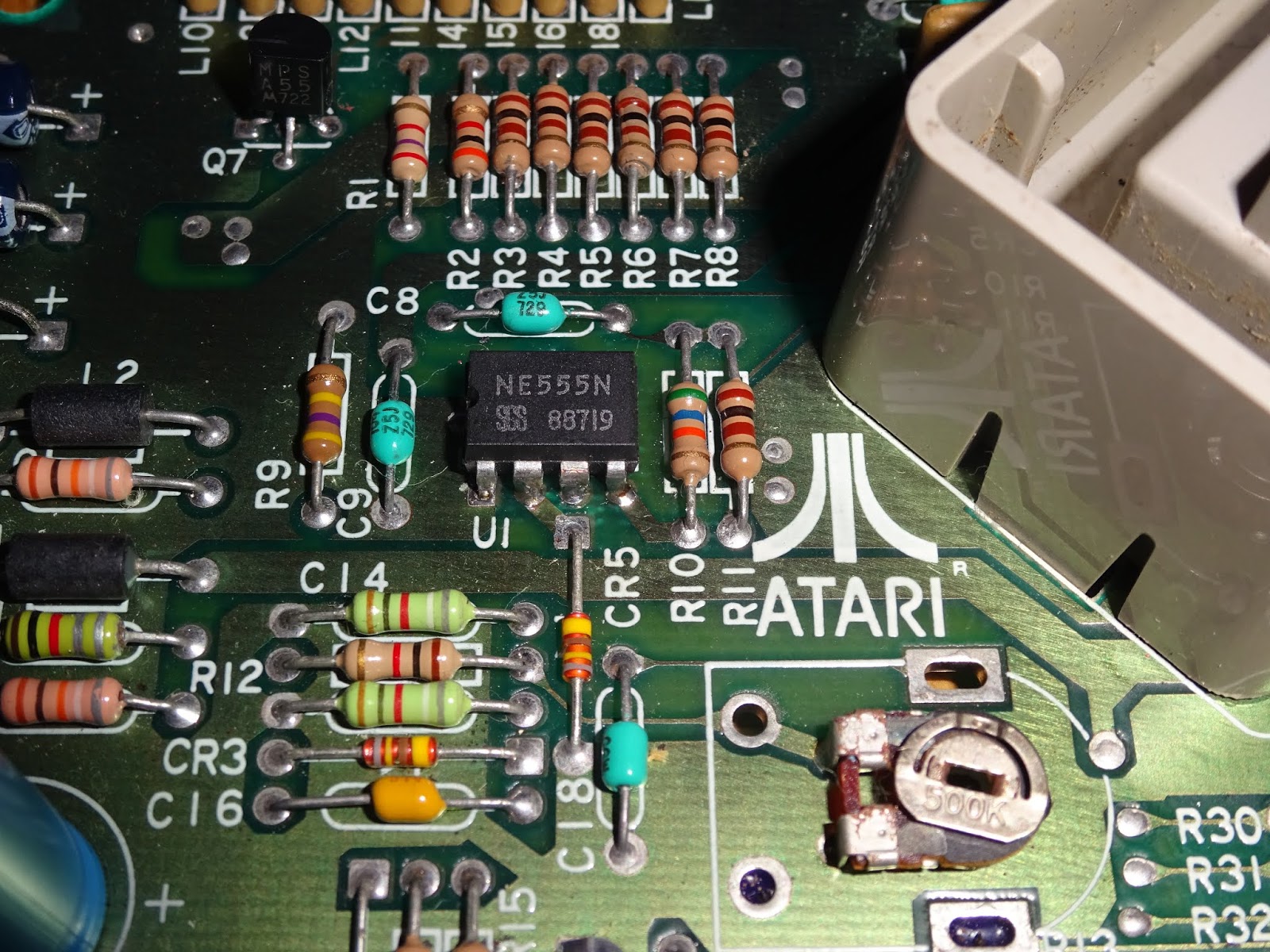
Firstly, the reset button was missing, and secondly, the 555 timer which generates the reset pulse had already been replaced. Here we go again.
There was no reset pulse on power on, and even shorting out the pads where the switch was didn't generate one.
With a new 555, we now have a reset pulse. Who solders a bad 555 back onto a board? Has someone taken parts from this one to fix another Atari and put the assorted broken bits back on this one. Several broken Atari's maybe?
I also fashioned a replacement reset switch out of a right angled tact switch, which came out to about the right height. So now we have power, clock and reset working, but still a red screen.
The RAM was socketed (this time in nicer turned pin sockets). I check the pins for continuity, and those were OK, but I'm really not happy about the other sockets, time for them to go.
With the board cleared, I could see a bit of damage beneath, but everything tested through OK.
With new sockets on, things were looking a bit better, but with a set of known working chips, there was still a red screen.
I tried a Star Raiders cartridge, useful for running up on almost dead systems, and it did start.
Or at least it went as far as the title screen. I could select the mission type, but whenever I tried to start the game, it would do nothing. I thought this might point to memory corruption, so I tried new RAM, but that made no difference.
The one chip I didn't have a replacement for was the MMU. This is actually equivalent to a GAL, so I programmed up a 16V8 with the appropriate equations and tried that. Nope, no change. I also tried the 74LS138 decoder in case that was causing the conflicts, but no.
There was still conflict on the databus. All that was left on there were the 6520 PIA and the GTIA. Neither of which had been originally touched.
Well, what do you know about that. the 6520 was bad as well. With that replaced with a W65C21N, the system booted up to the Missle Command screen. But it wouldn't start. Pressing reset brought up self test, but that wouldn't start either. Still problems?
Well, not exactly. Rather stupidly, I hadn't checked the actual switches. I had assumed since the reset switch had been removed, it was faulty, therefore the others would be OK. Wrong. Two of the others were also bad. That may explain why I couldn't start Star Raiders before. Always check the simple things first. I managed to get it running, but couldn't see the results as red and green boxes would look the same in monochrome.
I thought this might be something to do with the mods for the DIN video socket, so I removed the links to chroma and luma, and wired it as a standard composite video and audio output socket, so I could use the same cable as I use on the other Atari (and Commodore) computers. I traced the chroma signal from the outputs of the GTIA, and it looked good, but it stopped after a buffer transistor.
Ah, that would explain it. I fitted a new 2N3904 transistor and we had colour again, and the ROM and RAM tests all passed.
I was already sick of shorting the contacts to press start, so, looked for some replacement switches.
These ones were close enough, so I replaced all four.
The power button was OK, as it turned out it was a mechanical on off switch, rather than a soft power circuit as I had expected.
This was all looking good. I could now start and play the built in missile command game.
Since I had wired up the 5 pin DIN socket as something useful, I thought I would try to use it. It is currently fouled by the metalwork.
I marked out the section that was in the way.
A bit of Dremelling later, and that is clear.
The hole in the plastic case was already suitable enlarged.
With that all back together, time for some testing. The XEGS can play cartridges from the 400/800 and later XL and XE computers. How about a bit of Centipede?
As it has the XEGS has the peripheral port, it can also load from cassette. [grabs a Rodman tape from the pile]
As with many games, that is perfectly playable as it only needs the start / select / option buttons and the joystick. The XEGS has two standard 9 way D joystick ports, at the same 45 degree angle as the cartridge slot on the top.
On the other side, at an equally jaunty angle, is a 15 way D connector marked 'keyboard'.
Into that you can plug in the optional keyboard. As you can see here, mine came from a different system, one that spent a great deal more time soaking up those 80's UV rays.
With that installed, you now have pretty much a 65XE. It boots into BASIC and away you go. The keyboard is in fact the same as the 65XE
You can see at the top where the start / select / option and reset buttons would normally be fitted.
Underneath is a controller board containing the mux and demux chips which address the switch matrix.
So, that's the Atari XEGS. Back up an running.
In the end it turned out it was only a bad CPU. Oh and a bad 555. And a bad 6520. Oh, and that damaged cap. One broken transistor leg, two bad switches, and one missing, and let's not even mention the 5 pin DIN connector.
Ah well, I am going to have to do some more testing, there are two versions of Rodman on the Atari 8 bit, one in full colour
and one in monochrome, but with higher resolution graphics.
Atari 8-bit is one of the 8 systems on the 3 tape special edition of Rodman, now available to pre-order from The Future Was 8 bit.