Sunday 30 April 2023

Mini VIC Development Part 4 - Video out tests

The last of the Mini VIC development logs for the moment. From February 2022.


Over the years, I have come up with all sorts of ways of generating a video signal from a microcontroller. The different technique have pros and cons, and limits. The MiniVIC project has pushed the limits of the techniques and devices I have previously used, so I a need to explore some new ones.

Practically speaking, I need to generate sync signals and video data. For composite video, composite sync (CSync) is generated from a vertical sync and a horizontal sync (HSync), and then merged with the video data in the analogue domain.

Vertical sync is one (usually negative) pulse for each frame, at a rate of 50Hz or 60Hz depending if it's PAL or NTSC.

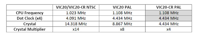
The frame is composed of a number of lines (312 / 262 for PAL / NTSC), each of which are 64uS, a rate of 15.625KHz (or 63.5us / 15.750KHz for NTSC).

It is very important when generating these signals that the timings remain consistent. Particularly the start of the HSync pulse. If that is out by only one microcontroller cycle, you will end up with wobbly vertical lines.

One of the things I wanted to play with was the Atmel Start tool for configuring a project and automatically generating code (start.atmel.com). From previous experience, I will probably end up refactoring the massive number of files it generates into a single file, and then likely re-implementing the whole thing in assembler anyway. But, let's give it a go, it seems to have a lot of potential.

You setup your project, pick your microcontroller, and then can graphically configure the peripherals on the microcontroller. It seems this is the only way to find out some things which are missing from the datasheet. I couldn't find the magic numbers to unlock the clock select register, or the truth tables for the logic cells, and had to reverse engineer the auto generated code to find them.

You get to add various modules for timers, USARTs, ADCs, Digital IO etc.

You can rename some of these to help, but the names don't follow onto all the pages, so you need to keep notes as you go along of what timers you are using for what etc.

You can also name pins etc. and setup each pin individually to set if they are input or output, set the initial states, pullups etc.

You can setup and link all the clocks, but in most cases you only have the choice of the main clock, but it's nice to see.

You can use the "events" system to link things together. In this case, I am linking the overflow of the horizontal counter to the count input of the vertical counter. This is one of the pages were you don't get to see your renamed modules so you have to remember which is TCA0 and which is TCA1 etc.

This means the vertical counter will automatically count up each time a horizontal line is completed. With the horizontal and vertical counters linked up, I have set them in waveform generation mode, which is automatically generating the HSync and VSync signals I need. This requires some initial setup code, but after that, it requires no code when it is actually running. It just sits there generating the precisely timed sync signals. That's a really neat feature.

Finally, there is the combination logic, which is like a GAL chip inside the microcontroller, and you can set that up just on digital IO, or you can reference the internal peripherals. In this case, I am generating the CSync output automatically from the horizontal and vertical counters.

This is one of the things I couldn't work out from the datasheet. Apparently !(A^B) is table number 9, but I had to search through the 160 files in the project that Atmel Start generates to find that. (note it also generates a load of commented out code, not sure that helps)

There are various definitions of what would composite sync should be. The simplest is just ORing the active negative sync pulses to so that CSync is low for the entire VSync period and all the HSyncs. This is not ideal as the TV can loose track of the HSyncs and can take several lines to get back into sync (leading to tearing of the image at the top of the screen). The second is XORing those signal, so the CSync is inverted during the VSync period.

This is better, but also not ideal as the transitions are a bit messy.

Finally there is the third version which is the correct one. It uses specially formatted lines with a pattern of shorter and longer HSync pulses during the VSync period. That is the version I generate in the Mini PET, and what I will end of doing on the Mini VIC, but for the time being, the XOR version will do fine.

Most of these peripherals have the options of driving several alternative pins, but these still seem to end up all over the chip. That is going to be a problem when I need several full 8 bit ports for the address and data busses, but I'll worry about that later.

My tinkering has lead to a usable display, with a few issues.

The vertical lines aren't perfect, which seems to be an issue with the USART output being used as a shift register to generate the video pixels. That is also an issue at the start and end of a line, leading to the thick first pixel, with visibly thicker pixels at the start and end of the lines.

I had problems aligning to the start and end of the USART data, which is going to be a problem synchronising this to the colour data which will need to change every eight pixels. At the end, I had to add a load of NOP instructions to wait until the data had completed being sent. The transmit buffer empty and data transmission flags both indicated it was clear, but there were still a byte and a half to send.

If I reduced the number of NOPs to try to tidy that up, it stopped working and would only ever send the first line. Here I toggle the invert bit on the output at the point it says transmission is complete. As you can see, it's no where near the end. The serial output is high when there is no data, so I planned to disable the USART and set it to a plain digital output set to low. That didn't work, so I ended up using the "invert this pin" setting to invert it, but that left the unsightly thick border at the end. A final option is just to keep sending 0x00 all the way to the start of the next line, but I'd rather not.

I think the USART in SPI mode (or SPI hardware itself) generating the pixel data is going to be problematic if I can't control when it starts or know when it stops.

One idea I had to get around that was to do the colour mapping internally and generate R, G and B pixel data, using three USART ports. In the capture below, yellow is the 4MHz dot clock used to clock these pixels out, and red, green and blue are their respective colour signals.

Here I am sending the character 0x42. Not for the obvious reason, but because it's a good character to test, 0100010, as you can see three times above. I was hoping I would be able to get them to synchronise, but they are not lining up. That will result in a white character with colour ghosting on one side or the other.

I had thought I would be able to send all three signals through a latch gated at the 4MHz dot clock, so the edges would like up (the same technique used on the Minstrel 3 to align the character and invert data). That would work as long they are not more than one pixel out from each other.

But unfortunately not, it is not consistent from line to line, and wobbles about more than one pixel so that's not going to work. You can just about see the visible wobble on a single USART in the black and white image.

I tried lots of different ways to try to get those into sync, but couldn't get it to work. I tried resetting the baud rate counter before sending the bytes to see if that would help. I also tried staging them with a precisely timed delay just less than 1 character before second the second one etc. Nothing seemed to work consistently from line to line.

In the previous posts I had a bit of a go at the autogenerated C code for the AVR microcontrollers from Atmel Start. You may think that was unfounded, or biased, or that I am a stick-in-the-mud-grey-beard-assembler-programmer. It is true that my beard does have grey bits in it (I am quite pleased that it is taking on a very Roger Delgado look at the moment). However, during this development, I caught an example of the sort of thing I was complaining about.

I present the case for the prosecution:

This is from the .lss file generated by the compiler which shows the assembly generated (in black) from the C (in grey). Here I am setting the three data output registers to the value of 0x42. This time it has generated fairly optimal code, it loads 0x42 into a register and then does three STS store instructions to set each of the USART registers.

I added some code above this to set the baud rates, but did not make any changes to the three lines of existing code below. However, it somehow messed up the display.

Looking at the .lss I can see why.

It has replaced the STS instructions with various store instructions relative to X, Y and Z registers. Granted STS is 2 cycles and most of those are single cycle, but with all the setup required, it's using more instructions that the STS would have been. 21 cycles if that was does just using LDI and STS vs 24 for that lot.

It also messed up the relative timing of the point at which the registers were set. Ideally, I would set all three at the same time, but that's not possible as far as I can see, so setting them two cycles apart I can keep track of things.

That wasn't the cause of the USART outputs not being in sync, but when it messed up the code it made it a lot worse, and more difficult to diagnose what was going on because the relative measurements all changed.

This is one of the reasons you can have a bit of code which works fine, you change something seemingly unrelated, rebuild it and it stops working. If you are working with less precise timing, it probably doesn't make any difference, but here just one cycle out can mess up the display. I need to write this stuff in assembler so that once it is correct and working, it will not change.

The prosecution rests.

I found the same degree of variation with the SPI ports. There are only two of them on the AVR Dx series of chips, so I couldn't do the RGB outputs with this chip, but I gave it a try. I couldn't get even two in sync. I also couldn't get the divide by 6 I needed for a 4MHz clock from the 24MHz master clock anyway.

But I could get 4MHz out of the USART ports. When operating in fake Master SPI mode, they generate a clock on the XCK pin. I tried using one USART, and connecting the clock output from the XCK pin to the SCK clock inputs of the two real SPI ports in slave mode.

Blue was the USART, and red and green were the SPI slave ports. This sort of worked, but suffered from the same drift problem as it was still derived from the USART. It also drifted too far later on so that the synchronisation latch wouldn't have worked. I also had problems controlling the levels when not transmitting data (I tried disabling IO, using internal and external pullups and pull downs).

I had better results with an external 4MHz clock, but that would only give me two of the colours, and it was still varying a cycle or two here and there. Running in slave mode also ties up 4 pins per port, as SS is required to enable the output, MISO is the data, SCK is the external clock and although MOSI is not being used, it still has to be set as an input.

So progress of sorts. I have a working composite video generator using just the microcontroller and few external components. All of the synchronisation pulses are being generated by the timers internally. The only code involved is to set this up. After that, they run on their own and the actual code can go away and do other things (i.e. generate the pixel data). That should mean it's all cycle exact and not relying on interrupts (which may occur 1-4 cycles after they are fired depending on how many cycles the current instruction has left, not to mention the function calling overhead)

It looks like I am not going to have sufficient control over when data is clocked out of the USART or SPI ports and that is not being consistent line to line, so I think I am going to have to go back to an external shift register, but it has been interesting to try different methods out, if only to prove that they are not going to be good enough in practice.


That is the last development log for the moment. I think I have gone as far as I can with the microcontroller version to prove it's not going to work unless I go to something like an ARM chip, and then may as well be a Raspberry Pi, and then may as well just run an emulator on there,

I moved on to doing a discrete logic implementation of the VIC, but that was getting a bit silly, almost taking up a 2 pin VIC20 sized PCB full of logic chips.

There are also at least two people working on CPLD VIC chip replacements, so I am not sure if I will need to continue down this road.

To be continued.......


Advertisements

Minstrel 4D

No Mini VIC kits any time soon, but the Minstrel 4D kits are shipping now, you can order one from The Future Was 8 bit - SPECIAL OFFER - £15 off the Minstrel 4D and free shipping to the USA

https://www.thefuturewas8bit.com/minstrel4d.html

More info in a previous post:

http://blog.tynemouthsoftware.co.uk/2022/08/minstrel-4d-overview.html


Patreon

You can support me via Patreon, and get access to advance previews of posts like this and behind the scenes updates. These are often in more detail than I can fit in here, and some of these posts contain bits from several Patreon posts. This also includes access to my Patreon only Discord server for even more regular updates.

https://www.patreon.com/tynemouthsoftware

Sunday 23 April 2023

Mini VIC Development Part 3 - Clocks and clocks and clocks and clocks.

The third Mini VIC development log. Lots of clock talk in this one from February 2022.

I need to address one of the points I glossed over in the list of things to do in the previous post. I am cheating a bit with a 4MHz dot clock. The VIC20 used something close to 4MHz, but the actual value is based on the video circuitry, and is generated by the VIC chip. This PAL VIC20 CR uses a 4.433618MHz crystal to generate the dot clock and it is divided down to get the CPU clock.

This is different between PAL and NTSC systems, and between the PAL 2 pin VIC 20 and the PAL 7 pin VIC20 CR. In all three different crystals were used in VIC20 systems.

I've shown the frequencies in terms of multiples of the CPU clock as that makes it a bit easier to see what is going on, although in practice everything is divided down from the crystal frequency rather than being multiplied up.

I have covered the differences between the three models, and conversions between them in previous posts, and also one on a multi region TED machine if you fancy that as well.

The microcontroller runs at up to 16Mhz, and it would be a lot easier if this were a multiple of the final dot clock and CPU clock I am looking to achieve.

Using the 16MHz timings for simplicity, one horizontal line of character on the VIC20 screen is 2us long. That is, the video signal wiggles up and down for 2us in a pattern of highs and lows that are turned into blue or white pixels on the screen.

These patterns are generated by clocking 8 bits of data out of the shift register with a clock that runs at 4MHz.

If the microcontroller ran at that same 4MHz, it will have just 8 instructions to fetch the next character from the memory and look up in the font ROM what pattern of bits it needs for the current line of that character, and load this into the shift register just in time for the next character.

That's a tall order in 8 cycles. If the microcontroller runs 4x faster at 16MHz, it will then have 4x as many cycles to achieve that task. 32 instruction cycles is still not many, but it should be enough. (I am glossing over at this time that it also needs to look up the colour, allow half of those cycles for the CPU to access the memory, and also check if the CPU has read from or written to any of the VICs internal registers - but lets leave that for the moment)

I have worked out two options for the microcontroller clock. One is 16x the CPU clock, the other is 14x the CPU clock.

The 16x CPU clock is 4x the dot clock. That matches the 1MHz / 4MHz / 16MHz ratio on my current test board. The 14X CPU clock is 3.5x the dot clock, the same ratio as the NTSC VIC20.

The x14 option gives 14.318 MHz and 15.518 MHz, which are both clear of the 16MHz limit, but give only 28 cycles per character, rather than 32. Not sure at this point how many of those I am going to need.

The 16x options gives a 16.364MHz / 17.734MHz clock for the AVR, which is a bit high for the chips rated at 16MHz. It's only 10% over, but is that too much of an overclock?

They quote voltages in terms of 4.5-5.5V (5V +/- 10%), but the tolerance of the maximum frequency is not given. If you external clock is 16MHz +/- 1% that could mean 16.160Mhz, which is also over 16MHz, but is that OK? Not sure

Why use those particular frequencies anyway?

Those odd frequencies are related to the colour burst frequency in the composite video signals.

 Generating those it a bit complicated. There are chips which will do it, such as the  LM1889 used on the ZX Spectrum and elsewhere - well out of production. The only one still in production (but out of stock obviously) is the AD724JR used on the Harlequin Spectrum clones. (Note the crystal is marked 4.433619MHz not 4.433618MHz as in the VIC20. It should be 4.43361875 MHz, so I guess the rounding on this crystal is more correct)

I am considering not bothering with colour composite video and just having black and white composite and RGB monitor or SCART connection, but I would still like the CPU to run at the original speed if possible.

I am not sure how best to deal with those different speeds to offer PAL and NTSC, maybe two external crystals or possibly one of those PLL chips which can generate any clock speed from a base crystal?

This is the SI5351, and it looks promising. It is programmed over I2C and generates three clock outputs at any frequency from 8 kHz to 160 MHz, including fractional values such as the ones I need.

It's a 3.3V chip, so the inputs and outputs are 3.3V. This (clone of an) Adafruit module includes a 3.3V regulator and level shifters for the I2C inputs (but not the outputs which will need separate buffers).

The calculations are a bit involved, I have worked out four sets (PAL and NTSC versions of 16x and 14x clocks). There is a program to help, but you still have to do quite a bit of juggling to get the best results.

The ratios are not shown there, but are calculated as follows:

NTSC = 315/88 = 3.57954545455

14.318181818 = 315/88 * 4

4.090909091 = 315/88 * 16/14       = 14.318181818 / 3.5

1.022727273 = 315/88 * 4/14        =  4.090909091 / 4

Here I am starting with the NTSC frequency as 315/88 which is the actual definition of the frequency in MHz, rather than just using rounding to a few decimal places, so it has lots of precision.

Internally, the chip starts with a 25MHz crystal, multiplies it up to a high common factor, then divides it down to get the final value.

25 MHz * 36 = 900 MHz

900 MHz / 880 = 1.02272727273 MHz

I don't know at this stage if I will need the divided down versions, or just the ~16MHz microcontroller clock.

The values here aren't exactly right, I'm not sure about the accuracy of the logic analyser, it's resolution isn't great at higher frequencies (even at 200MHz sampling).

For the moment I will leave it at 4MHz dot clock and 1MHz CPU clock and deal with the specific timings later.

The last point on this subject (I promise) is the alternate microcontroller choices. I am still considering the AVR128DA/DB range, it's going to take more work to get up to speed writing code for them, but the 24MHz clock would give me 48 instruction cycles per character rather than 32, which I might need. The Dx range also has an improved AVR core and some of the 2 cycle instructions in the old older ATmega range are now single cycle, including crucially SBI and CBI which set or clear an individual IO pin. That would also be helpful in squeezing as much into the 2us character window.

There is a bit of inconsistency in the datasheet. In several places it seems to imply these chips can use an external clock up to 32MHz, but it others it says the maximum is 24MHz.

The Atmel Start page won't accept values over 24MHz, yes it has a dropdown to select up to 32MHz external crystal (and there are matching bits in the register it sets). It seems it may be possible to use an external crystal oscillator at 32MHz, which would give me a luxurious 64 instruction cycles per character.

I have raised a support case with Microchip to see if they can confirm if 32MHz is supported. I have ordered some oscillator modules just in case, but I don't want to try it out in case I am overclocking the chip and fry it.

I'll call this one Bob.

2023 Update - it turns out you can use up to 32MHz crystal, but only if it is configured to be divided down to below 24MHz, which doesn't help here. 

The rest of this post is a mini rant, feel free to switch off now (if you haven't already).

I had to straighten three of the four pins on these modules, they arrived in individual plastic tubs. Good old RS, they love their excessive packaging.

Bob came a clear tub like that one, rattling around with no protection on the pins. I also ordered a surface mount version (above) in case it worked and I wanted to solder one directly to the module.

As much as I complain about RS, they do give me free next day delivery and no minimum order charges. I feel bad about ordering just a few pounds worth of parts and still getting free shipping. I often add more items to the cart to bring the value up, and then realise I have wasted my time when the end up getting shipped separately anyway.

Even though more than half of the listed items are out of stock, they have still not implemented an "out of stock" filter. I ended up having to check thirty or forty listing for 32MHz oscillators until I found one that ran at 5V and was in stock.

When I was there, I was amazed to see that the AVR128DB48 was in stock, so I thought I would add some to the order (in case I fried the one on the red board, or in case I made a PCB for this project later on).

So overjoyed to see a microcontroller in stock, I ordered some, and they arrived the next day.

Yes folks, I didn't see that they had listed the VQFN (nasty tiny square things with no legs) with a picture of the nice friendly TQFP chip.

Rant over.


Advertisements

Minstrel 4D

No Mini VIC kits any time soon, but the Minstrel 4D kits are shipping now, you can order one from The Future Was 8 bit - SPECIAL OFFER - £15 off the Minstrel 4D and free shipping to the USA

https://www.thefuturewas8bit.com/minstrel4d.html

More info in a previous post:

http://blog.tynemouthsoftware.co.uk/2022/08/minstrel-4d-overview.html


Patreon

You can support me via Patreon, and get access to advance previews of posts like this and behind the scenes updates. These are often in more detail than I can fit in here, and some of these posts contain bits from several Patreon posts. This also includes access to my Patreon only Discord server for even more regular updates.

https://www.patreon.com/tynemouthsoftware

Sunday 16 April 2023

Mini VIC Development Part 2 - Picking a Microcontroller (including USB Keyboard composite video mod)

This is the second of the Mini VIC development logs, previously Patreon exclusive posts. This one is again from January 2022, peak microcontroller shortage.

In the last post, I identified many of the things I need to do to progress from the proof of principle test. The first one is to pick a suitable microcontroller.

It needs to support the USART in SPI mode used to generate the video, and needs at least one 16 bit timer to trigger the various stages of the video waveform. It also need to be fast (16Mhz minimum, ideally a lot more), and must have lots of pins. Accessing the video RAM is going to need 20+ pins, so the humble ATmega328P is not going to cut it.

I've been trying out various boards, including these AVR128DA28 Curiosity Nanos. Quite a neat idea, there is a built in programmer / debugger at one end and all the pins are taken to pads on the end.

I picked up a few different versions of these with different microcontroller options. There are also PIC versions and the ARM cored SAM range.

The problem with this is the same as the SAMC range I looked at last year. Such a bloated framework with endless updates to get the simplest project loaded. Framework updates, package updates, studio updates, updates to the firmware in the programmer. And finally the "blink" project loads. It has created 121 files and folders, all to blink an LED.

It took me ages to go through all of those to find out what was actually being used. Full of unnecessary things like initialising each IO pin individually to the default values they would already be initialised to at reset, rather than just DDRA=0 etc.

Microcontroller datasheets used to be full of example code in C and assembler. This PIC databook got so much use back in the days of 16C54's and 16C84's etc. I don't think it left my desk for years, and even then was still close at hand on the nearest bookshelf.

The new ones don't seem to have any code examples in. I found one that didn't even have a pinout.

It took a lot of reverse engineering the output of the compiled C code to see how to set the clock - you have to write a secret value (which doesn't appear to be mentioned in the datasheet) to one register to unlock access to certain other registers.

Then just a simple delay loop to blink the LED.

I was hoping to use these new chips, either the AVR128DA48 or AVR128DB48, but I find this just too much hassle to wade through all the layers of frameworks to get down to what is actually required. I started looking at what was going to be required for the serial port and the timers and I gave up. The information wasn't there to do what I needed.

There was a way of generating C code that would do it, but with massively bloated interrupt handlers that were taking dozens of cycles saving all the registers each time. It gets messy to try to mix C and assembler as you can't always control which registers it is using, so when you need tight timing, as I do here, you end up writing it all in assembler.

The framework didn't appear to support the USART in SPI mode, it should be possible, but it looks like it might be more complicated with a second register containing a 9th bit which may also need to be set each time?

It's not a very good photo, but it took so long to get to assembly code flashing that one LED we are all going to look at it and appreciate it.

(2023 update: I did in the end spend an awful lot of time extracting the appropriate bits I needed to write the Minstrel SD code for one of these AVR chips for the Minstrel 4D project, and even used one of these development boards on the prototype.)

I think I'll go back to the older chips. They are slower (16Mhz vs 24Mhz), but some of the seemingly simple tasks I am trying to do take less cycles on the slower chips so actually work out not only easier to write, but faster. The newer chips do have single cycle port bit changes, which would help in the critical sections, so it's not entirely a win for the older chips.

One feature in particular I think will be needed here is the external RAM interface. This was only available on a few microcontrollers (usually the ones with a lot of pins), and allowed external static RAM to be addressed as part of the normal address space.

Even though there were loads of pins, all the chips I have found use a mechanism where the lower address bus and data bus are muxed, requiring an external latch chip and one extra cycle. 

The ideal would have been separate address and data busses, but I don't think any of the range are configured like that. It would also seem to have been a better option to mux the upper address bus instead, since that would likely be changed less frequently.

The alternative is to manually set the two bytes of the address, enable the address lines, toggle the read pin, read the data then toggle read off and then turn the address lines off., All of that will take many cycles more, and it is really tight with 16 cycles to read a character, work out the address in the font ROM, read the bit pattern from the font ROM and output that to the shift register. One of the reasons I kept with separate video ROM, character ROM and shift register in the Mini PET was that allowed me to do all that in just 8 cycles.

It's a tricky time at the moment to develop anything new, as so many parts are out of stock or limited availability, so I have been rummaging around to see what I have on hand that can do the job.

It's a bit old, but the ATmega2560 as used on the Arduino Mega is a possibility. This has several UARTS, loads of pins, and supports the external memory interface.

Looking around at other options, one that might not be an obvious choice is the AT90USB646, a chip I used in the larger USB keyboards.

The speciality of the chip is the USB interface, I don't actually need that here, and don't think I can use it, I would have to stop drawing the screen when the USB was accessed. What is this, a Commodore 64?

It is 16Mhz, has one USART which supports SPI, various timers, lots of pins, and it supports the external memory interface.

I do I have a few test boards from the early days of those, this one looks a good option. I have taken all the pins out to two pads, one of each of which I have soldered pins to.

The chips are still in production, but obviously are out of stock everywhere until next year, but the same is true of most microcontrollers, so I'm not really bothered. (2023 update, just checked and found some of these in stock! ordered.)

I am just going to plough on regardless and see what availability is like when this project is further down the line. I might move to another chip if needs be, but this seems a good starting point.

Surprisingly that lashup worked. The VIC20 test screen code running from the AT90USB646 board, with the resistors and diode on the breadboard that I was using to test the AVR128DB48 with, and the buffer transistor and composite output on the breadboard from the original Arduino ATmega328P tests.

That looks like it's worth taking further, so time for a composite video mod on a USB keyboard controller to make something for a vintage computer kit. (if that's not peak Tynemouth Software Blog, I don't know what is)

The phono jack fits quite nicely where the USB jack was, and I was able to reuse various pads to mount the transistor and wire up the signals to port B.

I have tidied up the code a bit in the move over, and will continue to tweak things. I notice the timer on this chip has three compare outputs rather than the two I was using on the ATmegas, so I should be able to set that up to do the front porch on the video signal.

When I was trying things out, I don't think I had noticed before how much nicer the PET / VIC20 font was.

This is the same screen, but using the font from the C64 and TED machines

I added that font when I was trying to see if I could get 40 columns. The current code is accessing hard coded video RAM and font ROM, so the number of cycles is going to changes when I switch to external RAM, but I just wanted to see if it would fit.

The characters are inverted here as the invert is actually a separate step, and I missed that out to try and get it to fit. The white lines you can see are where the next character was not available in time. The larger the gaps, the more instruction cycles over the limit it is. Here it was only a couple of cycles, but I had to unroll the code loop to get it to fit (i.e. cut and paste the code within the loop 40 times rather than having in check if a counter is less that 40 and looping back if it was, as that added three cycles per character).

The line timing is a bit out (the wobbly edges on the left), but I was more concerned to be able to get the characters out in time. Mini TED anyone?

The next step will be wiring up the external memory access. Lots of wires to solder to the test board. Part of that is going to need a 74HC573, and I don't seem to have any of those left. Plenty of HC574's (which aren't suitable due to the point the data is latched), and plenty of HC373's (which is essentially the right thing, but with an annoying alternating pinout).

In the past it was just a case of going to RS or Digi Key and clicking buy. This is 2022, so obviously, the standard Texas Instruments parts are out of stock everywhere.

I have managed to find an obscure Toshiba version of the same thing, with a whopping 80 of them in stock!

Once those have arrived, on to video RAM access.

More on that in the next post.

(2023 update - actually the next one is going to look at clocks and signal timing)


Advertisements

Minstrel 4D

No Mini VIC or Mini TED kits any time soon, but the Minstrel 4D kits are shipping now, you can order one from The Future Was 8 bit - SPECIAL OFFER - £15 off the Minstrel 4D and free shipping to the USA

https://www.thefuturewas8bit.com/minstrel4d.html

More info in a previous post:

http://blog.tynemouthsoftware.co.uk/2022/08/minstrel-4d-overview.html


Patreon

You can support me via Patreon, and get access to advance previews of posts like this and behind the scenes updates. These are often in more detail than I can fit in here, and some of these posts contain bits from several Patreon posts. This also includes access to my Patreon only Discord server for even more regular updates.

https://www.patreon.com/tynemouthsoftware