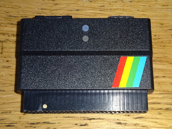
There are a bunch of new release from The Future Was 8 bit on cassette and cartridge, including some VIC20 titles. When there is a new VIC20 game, I like to get that ready to add to the next update to the Penultimate Cartridge.
First there was Super Monza Grand Prix.
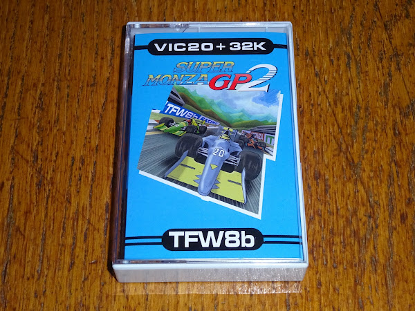
Then there was Super Monza Grand Prix 2.
Then there was a special TFW8b edition of Super Monza Grand Prix 2, with extra tracks.

Each side of the tape has a different set of track on. So there are two different versions of Super Monza Grand Prix 2 TFW8b edition, and ideally both of those would go into the Penultimate Cartridge.

I am also going to have to revisit the list of titles for some of the ones we have flagged as could potentially be dropped to clear some space (looking at you Q*Bert, how are you still in the cartridge?)
But it doesn't stop there. For the cassette release, TFW8b added a title screen and the option of reading a few pages of instructions before loading the game.

And since there were two version of SMGP2 with different track sets, there were two different introduction programs and two different games.

Both of these versions, and their intros are to be added to the Penultimate +2 Cartridge for the next update.
My first question was "can we have a single version with all the tracks?"
"No".
Oh. OK. Plan B, I would hope the track data might be at the end of the programs, and the majority would be the same, so I just need one copy of the main program and swap in one set of tracks or the other.
"No."
Ah. OK. It appears the game has been recompiled, as although much of the code looks the same, all the jump and data locations have shifted, so there is no commonality between the two versions. (I wasn't expecting there to be any commonality with SMGP1, and indeed there isn't).
So, we discussed the options, and didn't like the idea of having both versions on the main menu, three Super Monza Grand Prix is a bit much.

Ideally, the introduction program would be changed to ask the user to select the track set and then run the main program.
OK, that shouldn't be a problem......
......1 week later.....
My brain melted.
This one fought me all the way, but I finally managed to fit it into the cartridge.
Essentially I had to load one program (the introduction, now more a menu with instructions) and then let the user choose a set of tracks and then load one of two programs based on their choice.

After the user has selected their track set, they have the choice of showing the instructions, as before, or going straight into the game.

There were a couple of examples of that sort of thing already.
Final Orbit was actually a double title, Final Orbit and Bumper Bash. #NotMyCartridge

It always starts Final Orbit, but if you hit the Commodore key, it switched to Bumper Bash.

Both games were present in the 8K ROM. I guess some time in the 1980s, some executive was presented with a game which was something like 4.5K, so they had the bright idea of fitting a second game in what would otherwise be wasted space in an 8K ROM (which would have been more expensive that a 4K one if the game had been smaller).
Final Orbit had been in the cartridge for a while, with probably none of the users knowing the alternate game was there. When I added the live patching of games in the previous update (did I write about that?), I patched Final Orbit so it no longer switched, and added Bumper Bash to the menu with a different patch that meant it was locked in Bumper Bash mode, which is good as that is arguably the better game of the two.

Another example of this sort of thing is back in the early days of the Penultimate+ Cartridge. I had a Easter egg in the menu (which I don't think anyone found). Once you triggered it, the credits menu gained a new option "Tic Tac Toe".

When you selected that, it loaded a game of Tic Tac Toe, although it didn't say that (Some of you are probably old enough to get the reference.)

(I realise now I should have called it Falken's Maze, it's been a while since I watched that movie because every time I do I have to stop myself buying an Imsai 8080)
That lived at the end of the Spaceship Minus One ROM, as that game was about 5K and in those days I only had 8K slots so there was 3K spare and Tic Tac Toe was a simple BASIC program.

The 8K ROM is mapped into the VIC20 memory space at A000-BFFF. Space Ship -1 was a cassette conversion, a two part game. The first was a title / instruction, and the second the game itself.

As the first part was just loading a page of text, I added that to my normal ROM loader code so that it displayed that first, then went on to the game.
The actual Space Ship -1 game was stored in the ROM, but was copied into RAM at $1000 to run it (as if it had just been loaded from tape).

When the loader detected the Easter egg had been triggered, instead of showing the instructions and loading Space Ship -1, it copied a different game into RAM and ran that instead.

“The only winning move is not to play.”
Oh wait....

In those cases, both games fitted into a single 8K ROM. I have also converted several tape games into 8K or 16K ROM cartridges where the multiple parts are loaded into RAM and run, jumping back into the ROM with a SYS call to load the next part. (those are covered in excruciating detail in dozens of posts in the "converting multipart VIC20 games" series.)
This is different though, the two versions of Super Monza Grand Prix 2 (remember that?) are around 28K each, so I cannot load both into a 32K cartridge and then select one or the other.
The Penultimate works by switching banks of ROM to select different titles, but that is only controlled by the cartridge menu, and is disabled once a game is launched. I could use that mechanism to switch track sets, but I don't really want to have to enable it outside the menu. (since a game writing to the IO port could trigger the bank or mode switching which would stop it working - pretty sure Gorf does, I think related to the voice synthesizer it can use).
So, how am I going to do this?
Whilst looking at the options, TFW8b pointed out he had shrunk the tape versions using Exomiser. This is a self extracting compressor for PRG files. I hadn't looked into it before. The only experience I had with it were a bunch of games that were added at one point that didn't work properly on the cartridge and I had to ask for un-Exomised versions to get them to work.

You can spot it by a telltale flashing @ or A on the bottom right of the screen as the game is being decompressed.
However, TFW8b explained that was probably a problem with the command line options that had been used to generate the games I had been sent, so I investigated further.
And with the correct options it worked surprisingly well, getting both games reduced by about half.
Great, so now I could fit both games into a 32K block.
That was where things got complicated.
Time for some more diagrams. I hope the previous ones made sense, as these will be a bit more complicated.
Each 32K block in the ROM can be mapped into the VIC address space in various ways.
A recent update with direct loading of PRG files from those blocks, allowed files to be loaded from anywhere in the ROM to anywhere in the RAM.
I just need to make a menu program which runs and then copies one of the two games into position and runs them.
It took me a while to get my head around all the repositioning, particularly due to the gap at 8000-9FFF (character ROM, colour RAM, I/O etc.).
This means the file is contiguous in the ROM image, 0000-7500. This is copied to RAM 1200-7FFF and A000-A7FF

The menu is 0A00 bytes, and is copied from 0000-09FF in the ROM to 1200-1BFF in RAM.
The first track set version of SMPG2 is 3800 bytes, and is in the ROM from 0A00-4200. This is copied into RAM initially at 1C00-5400.
If the user selects set 1, the menu program needs to copy the game from 1C00-5400 to 1200-49FF. However, that would overwrite the menu program that was doing the copying, so I need some remote code.
I could copy code into the cassette buffer, but I can just as easily add a page of loader code at the end and just jump to that.
So that's what I did, and eventually (once I got my head around the addressing), it worked.

The final step is for Exomiser to expand the game back to 28K, which is does in place, and the game is ready to run.

Great, now for set 2. OK, strap in, this one is a bit more complicated. Maybe get that second cup of tea.
4200-6DFF in the ROM is copied into RAM at 5400-7FFF, and 6E00-74FF in ROM goes to A000-A6FF in RAM. (to get around the gap at 8000-9FFF)
That meant copying from 5400-7FFF in RAM to 1200-3DFF and A000-A6FF to 3E00-43FF. (note the second game is smaller than the first).
OK, here we go, let's try game 2.
Oh, it sort of worked, the flashing A in the corner showed it was decompressing, but locked up and stopped flashing.

It had started to decompress the program, so at least the start of the program was in the right place. I assumed I must have got the numbers wrong, so went back and worked them out again.
No, I had them right.
I tried various ways around and rewrote the copy routine in a slightly nicer way, but it still failed.
I then realised that this was all running from RAM, so I should be able to test it in the Vice emulator.
I copied the 32K ROM block form the cartridge and split it into the part that loads to 1200 and the part that loads to A000 and loaded those into Vice.

The number of times I had to type that in, I am still getting flashbacks.
Success, or rather failure. It did the same thing, and failed to decompress properly. At least I can debug it now and see what is going on.
First step is to check through RAM to see if the blocks were in the right place.
I went through checking the start and the end and for gaps in the middle, but it all seemed to be there.
So I saved the section of RAM and compared it to the original.

What? There were two bytes different in the middle of the file. Just two.
2BFE in the file was 4E and should be 16.
2BFF was 32 and should be 31?
I wasn't sure what was causing that, but I worked it backwards. 2BFF in the original file is copied into RAM to be run at 3DFF, and it is copied from 7FFF. Oh, that's interesting that's just before the 8000 gap?
I spent a while trying to work that one out, breaking at various places and checking for corruption, and also watching for reads and writes and finally caught a function in the BASIC ROM writing to that address. Eh?
Well, it seems that is some sort of temporary storage, set at address 55. It is 00 at boot, so gets set somewhere, and when I tried to change it, but it got reset to 7FFF, the top of the RAM that BASIC can see.
There didn't seem anything I could do to stop BASIC writing there, any time I moved it, it decided it liked 7FFF better than anything I suggested, so switched back.
I went for an awful bodge just to test this out, and poked the correct values into those two locations before running the game, and it worked!

Maybe I could live with that bodge? I then had a horrible thought, if this is caused by BASIC, will it be worse if I go through the extra pages of instructions?

Yes, it broke it as well, now more bytes were damaged.
To test it, I wrote 0 to the bytes in that area, then ran the menu through to the last page of instructions.

Yes, more things were getting corrupted.
Less of a bodge(?), I added a routine copy the last page of data from 7F00-7FFF to spare RAM at A800-A8FF. (it doesn't need to be 256 bytes, but it's easier to just do the whole block and it gives BASIC lots of space to trash stuff).
Then it was just a case of a nice and easy three stages coping blocks from 5400, A800 and then A000. (I did consider trying to split the file in two in the ROM image and introduce a gap, but I didn't want to have to mess with the PRG files in case they get updated in future.)

And finally, that worked.
Well, that was an awful lot of work, head scratching and brain melting, but I got there in the end. I hope the game is worth it.
There are now just two Super Monza Grand Prixes in the menu.

One a side note, in the process of doing that, I got quite adept at using the Exomiser to compress games, and have found quite a few titles in the cartridge that compressed by 25% to 50%, so I won't actually have to remove anything to add the new games, in fact, I freed up enough space to add several more titles.
So I am currently writing one in raw assembler, which seemed like a good idea at the time.
Wish me luck.
Advertisements
The cassette version of Super Monza Grand Prix 2 is available on cassette from TFW8b.com, along side another V2 game, Pentagorat II, now downgraded to the C64. And don't forget there is a triple pack option where you can choose three £4.99 games for £13.49. (all prices exclude VAT)

Also for the C64 is a great new graphical adventure game, Kingdom of the Seven Stones.

The updated version of the Penultimate +2 will be available shortly, alongside the new Penultimate +3, which adds an internal SD2IEC. More on that in a future post. (I guess I need to write an office suite for the Penultimate +4)

#NotMyBench
There is also my store with the full range of Minstrel and Mini PET accessories. Mini PET kits are all sold out now, but I do still have some Minstrel 3 kits left, which will last until I run out of Z80s.
I can ship worldwide, use the link at the top of the page to contact me with your location and what you want. Sorry I have to keep saying that. I am working on an alternative.

All the links can be found here:
Patreon
You can support me via Patreon, and get access to advance previews of posts like this and behind the scenes updates. These are often in more detail than I can fit in here, and some of these posts contain bits from several Patreon posts. This also includes access to my Patreon only Discord server for even more regular updates. If you want to see more posts like this, it would be great if you could give me a bit of support on Patreon, or via the PayPal link at the top of each blog post.